


-26-
Model G0701 (Mfd. Since 9/17)
Note: If you choose, you can remove the two
lower cap screws and the upper hex bolt that
secure the blade guard, then have another
person hold the guard out of the way while
you adjust the upper blade guide and support
bearings.
Make sure to firmly secure the blade guard
in place when you have completed the
adjustment.
4. Loosen the rotation adjustment bolts, then
use the knurled knobs to move the guide
bearings away from the blade.
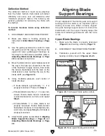
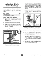
5. Loosen the guide block cap screws, then
rotate the blade guide assembly side to side
until the face of the support bearing is per-
pendicular (90°) to the blade, as illustrated in
Figure 26.
Bandsaw
Blade
Support
Bearing
Figure 26. Support bearing 90° to the blade.
6. Re-tighten the guide block cap screws to
secure the support bearing position.
7. Loosen the support bearing shaft adjustment
bolt and the lateral rod adjustment bolt (see
Figures 24–25).
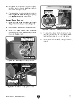
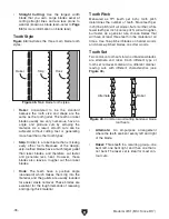
8. Adjust the blade guide bearings until the
edges of the bearings are
1
⁄
64
" (approximately
the thickness of four pieces of paper) behind
the blade gullets, as illustrated in
Figure 27.
Note:
With larger blades it may not be pos-
sible to reach the
1
⁄
64
" spacing. In this case,
adjust the bearings as far forward to the
blade gullets as possible.
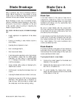
9. Position the support bearing so that it is
1
⁄
64
"
(approximately the thickness of four pieces
of paper) behind the blade, as illustrated in
Figure 28.
Note: The goal is to position the support bear-
ing so it will support the blade when pressure
is applied during the cutting operation.
1
⁄
64
"
Figure 28. Support bearing properly positioned
behind the blade.
Support
Bearing
Figure 27. Lateral adjustment of guide bearings.
Blade
Gullet
Bearings