


G0620 Main Control Panel
-9-
Combining
Adjustment Entries
The controller has the ability to combine numeri-
cal input entries of the blade height, blade tilt, and
rip fence without closing the input cycle after each
entry. This is typically the most efficient way to set
up a new cut.
To enter multiple entries, follow the same steps
for numerical adjustments with each control, but
wait to press the Start
key until after the last
control input has been entered.
Example:
If you want to set up a cut with a blade
height of 2.25", a blade tilt of 22.5°, and a cut-
ting width of 18.25", you would do the following
steps:
1.
Press the blade height key.
The indicator light on the blade height key
shines to show that the control panel is ready
to accept input.
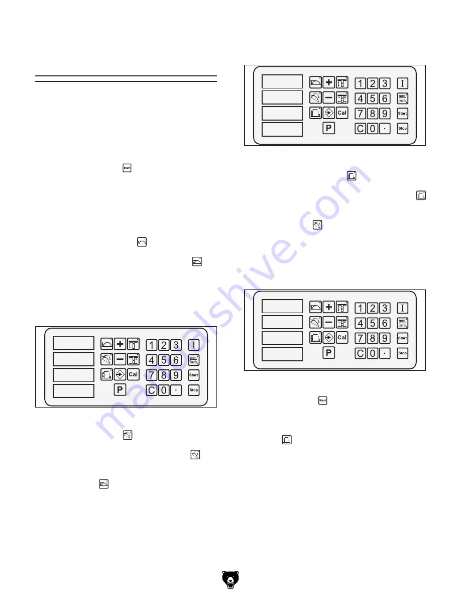
2.
Use the number keys to enter the blade
height (
Figure 12
).
����
�
�
����
Figure 12.
First entry.
����
����
�
����
Figure 13.
Second entry.
����
����
�����
����
Figure 14.
Third entry.
3.
Press the blade tilt key.
The indicator light on the blade tilt
key
shines to show that the control panel is ready
to accept input. The indicator light on the
blade height key no longer shines, but the
numbers previously entered still flash.
5.
Press the cutting width key.
The indicator light on the cutting width
key shines to show that the control panel is
ready to accept input. The indicator light on
the blade tilt
key no longer shines, but
both numbers previously entered continue to
flash.
6.
Use the number keys to enter the cutting
width (
Figure 14
).
7.
Press the Start key.
All components will move to their respective
positions and the indicator light on the cutting
width key will stop shining.
4.
Use the number keys to enter in the blade
angle (
Figure 13
).


