19
5.
4.
The spindle gibs ensure there is no play in the
spindle that could cause it to wobble.
To adjust the spindle gibs:
1.
DISCONNECT SHAPER FROM POWER
SOURCE!
2.
Elevate the spindle to its maximum 3"
height.
3.
If there is movement, adjust the gib against
the elevation housing, using the adjustment
screws at the top and bottom of the elevation
housing.
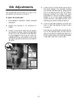
Figure 17
shows the two upper gib
adjustment screws and locknuts. One of the
two lower adjustment screws is also visible in
the photo.
Loosen the four 12mm locknuts and remove
the slack between the elevation housing
and spindle cartridge slide by tightening the
four
5
⁄
16
" setscrews with a 4mm hex wrench.
Alternate between the upper and lower
adjustments to ensure consistent tightness.
Failure to do so may cause disappointing
results. DO NOT over-tighten the gib. Over-
tightening will restrict spindle movement.
Loosen the spindle assembly lock knob and
raise or lower the spindle to check for free
movement.
Since there is an unbalanced weight distribu-
tion on the cartridge slide, you may have to
perform a number of adjustments before you
find the ideal location. Don’t get discouraged;
it may take a few tries to get it right.
Gib Adjustments
Figure 17.
Gib adjustment screws.
Upper Gib
Adj.
Screws
Lower
Gib Adj.
Screw
Содержание G1026
Страница 1: ...2 HP SPINDLE MOULDER INSTRUCTION MANUAL ...
Страница 2: ... 1 ...
Страница 4: ... SECTION 1 SAFETY 3 ...
Страница 5: ... 4 ...
Страница 9: ...Hardware Recognition Chart 8 ...
Страница 22: ...21 ...
Страница 23: ...22 ...
Страница 24: ...23 ...
Страница 25: ...24 ...
Страница 26: ...25 ...
Страница 27: ...26 ...
Страница 28: ...27 ...
Страница 29: ...28 ...

