background image


SINEWAVE GRINFINEON CONTROLLER MANUAL 

Rev 2.1 


-10- 

Of the 36 possible ways to map the hall and phase wires, only 3 will spin the 
motor properly in the forwards direction. Another 3 combinations will spin the 
motor in reverse, and the remaining 30 combinations will either not turn the motor 
at all, or will turn it with great inefficiency.  

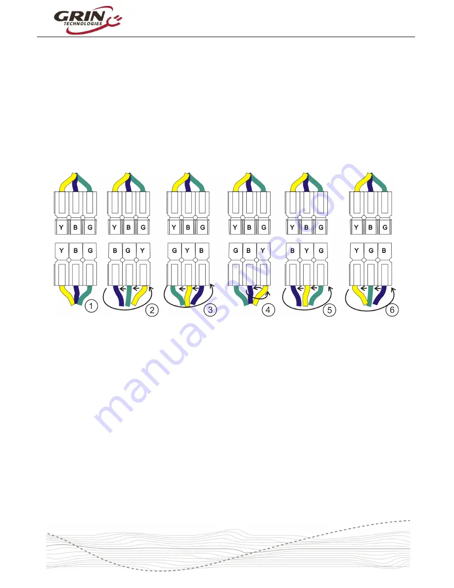
We recommend using a systematic approach to determine the hall and phase 
mapping. First, plug together the hall wires in any pinout that you like. Then 
connect the 3 phase wires together and test the motor. If it spins smoothly with 
low current draw, then great. If not, then separate the Anderson phase plugs 
(they dovetail slide into each other) and keep cycling through the 6 possible 
alignments testing each one. An easy way to keep track of this is by first ‘rotating’ 
the phase connectors through the first 3 positions as shown below. 


Figure 9: Systematic Approach to Phase Pinout Mapping 


Then swap any pair of plugs (yellow and blue swapped in above example), and 
rotate through the 3 positions again. This will cover all 6 possible phase pinouts, 
and one of those 6 should allow the motor to run smoothly.  

If that one position spins the motor backwards, then you can swap a pair of the 
hall sensor wires, repeat the test to find the correct phase pinout and it will spin 
the forwards direction.  

Be aware that there are some incorrect hall/phase pinouts which will still spin the 
motor when you apply throttle, but the motor will turn with great inefficiency and 
draw higher than normal current, usually with a small ‘kick’ when the throttle is 
first applied. You do not want to run the motor under load in this condition.  

When the motor is running in sensored mode, the LED will be on steady without 
blinking unless there is a fault error.  In sensorless mode, the LED will flash at a 
slow ~1 Hz rate.  

Содержание C4820

Страница 1: ...The SineWave Grinfineon Motor Controller User Manual Rev 2 1 Grin Technologies Ltd Vancouver BC Canada ph 604 569 0902 email info ebikes ca web http www ebikes ca Copyright 2017 ...

Страница 2: ...LED Indicator 11 3 3 On Off Switch 12 3 4 Regenerative Braking via Ebrake 12 3 5 Proportional Regen via 0 0 8V Throttle Signal 13 3 6 Fwd Rev 14 3 7 Fault Tolerant Hall 15 4 Limitations 15 4 1 eRPM Sensorless Sensored 15 4 2 Power Oscillations at Full Throttle when Sensored 16 4 3 60 Degree Hall Timing 17 4 4 No Change to Internal Settings 17 4 5 Max Regen Voltage 17 4 6 Won t Show CA Accessory Cu...

Страница 3: ...about any geared or direct drive brushless motor in the 500 3000 watt power range 1 1 Key Features Here are some of the features that make this controller stand out which you won t usually find with most 3 rd party ebike motor controllers Long phase leads 120cm On Off Switch Proportional Regenerative Braking Dual Mode works With and Without Hall Sensors Silent Sine Wave Operation in Sensored Mode ...

Страница 4: ...ations and orientations Although it is tempting we do not recommend putting the controller inside a bag or enclosure box that blocks exposure to air flow as it will be more susceptible to overheating The silicone grommets on the controller end plates do an excellent job of keeping water out so there is little concern about having the controller exposed to the elements and the orientation of the in...

Страница 5: ...Effect throttle devices It supplies 4 3V to power the throttle plug and expects a signal of 0 9V 3 6V as the throttle is twisted Throttle signal voltages higher than 4 0V are considered a fault condition so if a potentiometer based throttle is used then appropriate resistors are needed to keep the voltage swing within range Figure 4 Controller Throttle Pinout ...

Страница 6: ...u are running the motor sensorless then it is only these 3 wires you need to connect and the color pairing does not really matter If the motor spins backwards then simply swap any pair of wires to reverse it Figure 5 Example of Motor Direction Change by Swapping Phase Wires If you want regenerative braking in a basic setup then you can connect either an ebrake cutoff lever or other momentary push ...

Страница 7: ...ay of all your vehicle and battery stats The system still responds the same way to your throttle but the V2 Cycle Analyst has the ability to over ride and limit the throttle signal if you are exceeding the CA s programmed current limit speed limit or battery low voltage cutoff Figure 6 CA V2 Hookup Throttle and eBrake Plug into Controller motor and battery not Shown ...

Страница 8: ... Cycle Analyst rather than to your motor controller Only the 6 pin CA DP plug of the controller is used Figure 7 CA V3 Hookup Throttle and eBrake Plug into CA not controller The V3 Cycle Analyst is useful when much more advanced control features are desired like PAS operation motor over temperature protection torque sensing pedalec mode presets etc ...

Страница 9: ...ommend connecting them to the controller as well so that you can benefit from sensored sinusoidal operation The hall sensor plug has 5 wires red and black supply power to the hall sensors in the motor and the yellow green and blue wires carry the resulting hall signals Figure 8 Hall Signal Plug 2 4 Hall Phase Mapping Procedure Previous generations of Grinfineon controller had the ability to automa...

Страница 10: ...e connectors through the first 3 positions as shown below Figure 9 Systematic Approach to Phase Pinout Mapping Then swap any pair of plugs yellow and blue swapped in above example and rotate through the 3 positions again This will cover all 6 possible phase pinouts and one of those 6 should allow the motor to run smoothly If that one position spins the motor backwards then you can swap a pair of t...

Страница 11: ...state it s in and most importantly if there are any fault conditions that would cause things not to work The following are normal operating modes LED Off No power to controller either battery is disconnected or ON OFF switch is OFF LED Slow Flash Controller powered up throttle is not pressed or it is running but in sensorless mode LED Steady On Controller is running the motor in sensored mode The ...

Страница 12: ...g at least 20 AWG 3 4 Regenerative Braking via Ebrake The Grinfineon controllers have regenerative braking capabilities allowing you to use the hub motor as a brake and return kinetic energy back into the battery pack This can be achieved either with the ebrake lever for a constant 50 braking force or with a 0 0 to 0 8V throttle signal for variable 0 100 braking In the first method you connect an ...

Страница 13: ... 0 0V to 4 0V Figure 13 Regen intensity for throttle 0V 0 8V The test was done with the motor spinning at 100 200 and 300 rpm You can see that at lower RPMs the breaking intensity was higher for a given throttle voltage Even though the regenerative braking intensity is reduced at higher speeds the actual regen current flowing into the battery pack increases at high speeds as there is more mechanic...

Страница 14: ...e throttle line If you have a geared motor or mid drive motor then the regen won t have much effect It will cause the motor to quickly stop spinning when you squeeze the brakes but it won t be able to help slow the bike down due to the intrinsic freewheel of these systems There is no need to disable controller regen in this situation it is harmless 3 6 Fwd Rev If you have an application where the ...

Страница 15: ...e tried to make this controller fairly universal there are also more than a few limitations that can affect its use in some applications 4 1 eRPM Sensorless Sensored The maximum commutation frequency in sensorless mode is about 28000 eRPM This is substantially higher than previous Grinfineon controllers 13000 eRPM and will work with most geared hub motors just fine at typical ebike speeds but may ...

Страница 16: ...utation timing can be off and motor performance will suffer 4 2 Power Oscillations at Full Throttle when Sensored In sensored sine wave mode the motor controller is always attempting to interpolate the exact motor position at any given moment in between hall sensor events With certain geared hub motor installations the controller can be prone to having large power fluctuations at full throttle whi...

Страница 17: ...ower limits then either a V2 or V3 Cycle Analyst will provide that functionality and a lot more just via modulation of the throttle signal 4 5 Max Regen Voltage The maximum regen voltage is set to 58V for the 25A and 35A controllers allowing them to work with up to 14s 52V lithium batteries but without risk of high voltage spikes if the battery BMS circuit trips The 40A controllers have a maximum ...

Страница 18: ... of the motor and controller but not the current draw of any other devices like front lights that are plugged into the CA s power tap If you want the Cycle Analyst to show auxiliary device current then the controller can be opened up and the black wire from the CA DP cable moved from the side of the shunt adjacent to the blue wire to the side of the shunt adjacent to white wire ...

Страница 19: ...echanical C4820 C4825 C4835 C7240 Dimensions mm 110x71x34 154x87x46 Weight kg 0 47 0 49 0 75 0 78 Chassis Material Extruded Aluminum DC Battery Connector Genuine Anderson Power Poles Motor Phase Connector Genuine Anderson Power Poles Hall Sensor Connector JST SM Series Other Signal Connectors JST SM Series Waterproofing Gasketed at end plates and wire exits sealed switch 5 3 Connector Pinout White...

Отзывы: