Greyline Instruments SLT 5.0 Скачать руководство пользователя страница 33


Page 33 

SLT 5.0 Level and Flow Monitor 


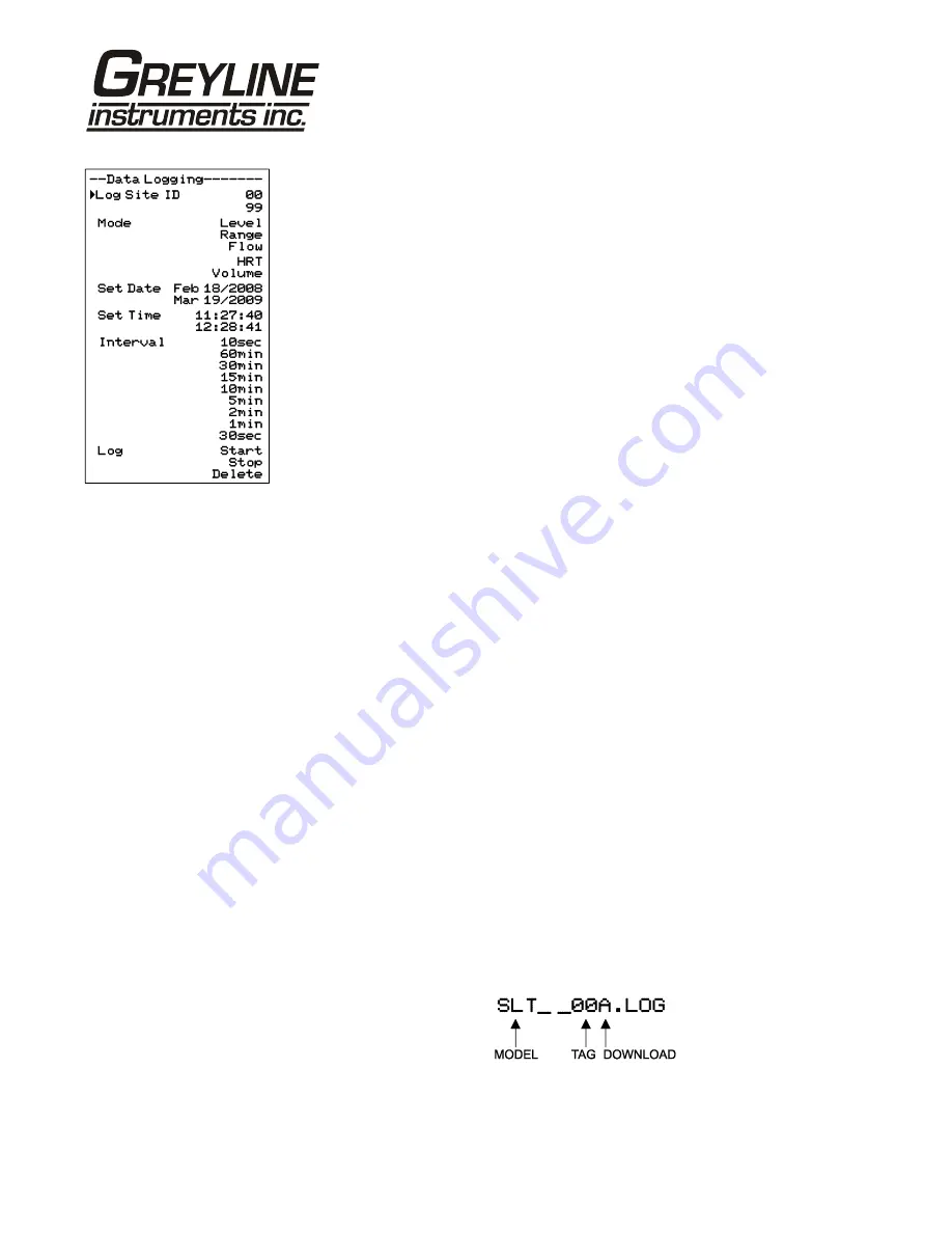
DATA LOGGING (Optional) 


Setup 

 
Select Data Logging from Menu Selections. 
 

Log Site ID 

Enter a number from   

00

   to   

99

.   The site ID will 

become part of the downloaded file name to help 
distinguish downloads from different instruments. Press 


to store the setting. 

Mode 

Select   

Level

,   

Range

,   

Flow

,   

HRT  

 and 

Volume

 .   

Flow

   (e.g. USGPM or l/sec). Press 

 to store the setting. 

Set Date 

Press 

 or 

 to scroll and select Month, Day and Year. 

Press 

 to store the setting. 

Set Time 

Press 

 or 

 to select the current time in Hours, Minutes 

and Seconds. Press 

 to store the setting. 

Interval 

Press 

 or 

 to select the logging interval. Flow rate 

reading will be stored at each time interval. Press 

 to 

store the setting. 
 
Note: Press 

 to Log 

 and 

 or 

 to Delete and 

 to 

delete the log file. Press 

 and 

 or 

 to Start and 

 to 

restart the logger. 

Log  

Stop

,   

Start

   or   

Delete

   the log file. Delete old file and 

start a new log to apply any changes that have been made 
to the   

Log Site ID

,   

Mode  

 or 

Interval


RETRIEVE LOG FILE 

 
Plug a USB Flash Memory Drive (not supplied by Greyline) into the USB output 
cable from the instrument. The instrument display will show the message 
Downloading until the log file is transferred to the memory card and then display 
Completed. The USB flash drive may be removed. 
 
Download file names will appear in this format: 

Tag is set according to the Log Site ID entered in the instrument Data Logging 
menu. 


Download letter will be A for the first download from an instrument. B for the 
second, then C etc. At the letter Z a - character will appear indicating that the 

Содержание SLT 5.0

Страница 1: ...www greyline com USER S GUIDE Installation Operation Instructions Level Flow Monitor Model SLT 5 0 Manual Series B 1 4 ...

Страница 2: ...Note This page has been left blank intentionally ...

Страница 3: ...ENSOR MOUNTING METHODS 20 APPLICATIONS HOTLINE 27 PRODUCT RETURN PROCEDURE 28 APPENDIX A OPTIONS 30 DATA LOGGING Optional 33 CONVERSION GUIDE 35 SPECIFICATIONS 36 IMPORTANT NOTE This instrument is manufactured and calibrated to meet product specifications Please read this manual carefully before installation and operation Any unauthorized repairs or modifications may result in a suspension of the ...

Страница 4: ...IMPORTANT NOTE To comply with CE electrical safety standards AC power input and relay connection wires must have conduit entry to the instrument enclosure Installation requires a switch overcurrent fuse or circuit breaker in the building in close proximity to the equipment that is marked as the disconnect switch Risk of electric shock Loosen cover screw to access connections Only qualified personn...

Страница 5: ...Page 5 SLT 5 0 Level and Flow Monitor CONNECTIONS ...

Страница 6: ...s show the four directions to leave a menu box Pressing a corresponding keypad arrow will move to the next item in the direction shown Move the cursor underline under numerals and increase or decrease numerals with the and keys To store calibration values permanently even through power interruptions press the ...

Страница 7: ...Page 7 SLT 5 0 Level and Flow Monitor CALIBRATION MENU ...

Страница 8: ... are being generated by the instrument Refer to the manual section Error Warning Messages for a description Press to return to the main display STATUS Press from the RUN display to view instrument status Range will be displayed in linear units Tot Displays the current totalizer reading EC Displays echo confidence Relays Energized relays will display as a white character on a black background 24 HR...

Страница 9: ...get to Password Factory default password is 0000 and if it has not been changed press the to proceed to the Menu Selections screen If a password is required press to place the cursor under the first digit and or to set the number then to the second digit etc Press or to proceed to the Menu Selections screen A new password can be stored by going to Special Functions New Password ...

Страница 10: ...he SLT 5 0 to calculate and display volume units in a horizontal round tank Flow mode is for open channel flow through a flume or weir From Volume HRT or Flow press to make your selection Range or Level mode will bypass the Volume units selection menu Volume Hrt or Flow modes will give you the additional choice of volumetric units ft3 cubic feet USG US gallons USMG US million gallons FLOW only IG ...

Страница 11: ... SLT 5 0 s response to level changes and is ideal to smooth the display and outputs in turbulent conditions Damping value is shown in percent 0 99 Some experimentation may be required to select the optimum damping value A value of 1 is recommended for most applications For fast level changes up to inch sec 13 mm sec a Damping value of 1 is recommended LOE Time Press and or to change the number of ...

Страница 12: ...vel press to view the Range reading in the Status menu Use this range measured by the SLT 5 0 as the Max Range setting or b Carefully measure distance from sensor to zero level with a tape measure and use this measurement as the Max Range setting MINIMUM RANGE At CALIBRATION Press to get to Min Range Press to move the cursor under the digits Use or to set the minimum range Note Min Range must be a...

Страница 13: ... Distance from sensor to Max Level Minimum range MAX RANGE MAX LEVEL must be at least 8 20 3 cm depending on sensor model 2 Check the maximum range with the sensor installed by a When liquid is at zero level press to view the Range reading in the Status menu Use this range measured by the SLT 5 0 as the Max Range setting or b Carefully measure distance from sensor to zero level with a tape measure...

Страница 14: ...Page 14 SLT 5 0 Level and Flow Monitor CHANNEL SETUP ...

Страница 15: ...and set the relay On and Off set points Pulse Press and set digits to the flow volume increment required between relay pulses Use this feature for remote samplers chlorinators or totalizers Minimum time between pulses is 2 25 seconds and pulse duration is 350 milliseconds Level Press to Mode and to select Pump Low Alarm or Hi Alarm Note Function setting Level will change according to selections ma...

Страница 16: ...for backlight for 1 minute after a keypress and then backlight off until a key is pressed again Reset Totalizer Press and select Yes to erase and restart the totalizer at zero Restore Defaults Select Yes and press to erase all user settings and return the instrument to factory default settings New Password Select any number from 0000 to 9999 and press Default setting of 0000 will allow direct acce...

Страница 17: ...um Flow Range or Level and to output 20mA 5V to the analog channel Select Minimum and press to simulate minimum Flow Range or Level and to output 4mA 0V to the analog channel To simulate and intermediate Flow Range or Level set Test to Actual and then enter a value for the Flow Range or Level The analog output and control relays will respond to the simulated value ...

Страница 18: ...s Each SLT 5 0 Level Transmitter includes a non contacting ultrasonic sensor The sensor must be installed in a position to obtain unobstructed echoes from the liquid or material being measured Mount the sensor away from pipes ladders or structural members which might cause continuous false echoes ...

Страница 19: ...a inch isolation coupling which MUST be used in your installation A threaded nipple or length of conduit may be used to position the sensor at the desired height The sensor should be hand tightened like a light bulb by turning the sensor stem only DO NOT use a wrench and do not over tighten DO NOT clamp the sensor below the isolation coupling ...

Страница 20: ...Page 20 SLT 5 0 Level and Flow Monitor SENSOR MOUNTING METHODS ...

Страница 21: ...lume manufacturer s directions for transducer location The transducer should be centered above the flume approach section and mounted 8 203 mm minimum above the maximum liquid level depending on sensor model The transducer should be protected from physical damage and the transducer cable should be routed in a separate metal conduit Because the sensor is equipped with a temperature sensor it should...

Страница 22: ... or more above the highest water level 2 PALMER BOWLUS FLUMES Position the sensor at the flume Diameter upstream from the throat of the flume Sensor height must be 8 203 mm or more above the highest water level 3 V NOTCH WEIRS Position the sensor at 3 x maximum Head upstream from the weir plate Sensor height must be 8 20 3 cm or more above the highest water level STILLING WELLS Stilling wells are ...

Страница 23: ...r ZERO POSITIONING OF SENSOR Open Channel Flow Applications Locate the sensor at the position upstream from the throat of the flume or weir plate as recommended by the manufacturer A technique for accurate sensor height adjustment is shown ...

Страница 24: ...ER 1 Open hinged enclosure cover 2 Insert 8 screws supplied through the four enclosure mounting holes to secure the enclosure to the wall or mounting stand Additional conduit holes can be cut in the bottom of the enclosure when required Use a hole saw or Greenlee type hole cutter to cut the required holes DO NOT make conduit wiring entries into the top of the enclosure Note This non metallic enclo...

Страница 25: ...0 Level and Flow Monitor PZxx Series Sensors Troubleshooting Resistance measured between the shield and center wire across the coaxial cable ends by mulitmeter indicates ambient temperature Resistance vs Temperature ...

Страница 26: ...evel and Flow Monitor FUSE REPLACEMENT 1 Turn OFF power 2 Loosen cover screw and open 3 Remove power module 4 Locate fuse on Power Board 5 Replace fuse with 2 AMP 250V 5 x 20mm fuse 6 Reinstall power module into chassis ...

Страница 27: ...ales Representative write to Greyline or phone the Applications Hotline below United States Tel 315 788 9500 Fax 315 764 0419 Canada Tel 613 938 8956 Fax 613 938 4857 Toll Free 888 473 9546 Email info greyline com Web Site www greyline com Greyline Instruments Inc Canada USA 16456 Sixsmith Drive 105 Water Street Long Sault Ont K0C 1P0 Massena NY 13662 ...

Страница 28: ... the Sensor Product Important unclean products will not be serviced and will be returned to the sender at their expense 1 Rinse sensor and cable to remove debris 2 If the sensor has been exposed to sewage immerse both sensor and cable in a solution of 1 part household bleach Javex Clorox etc to 20 parts water for 5 minutes Important do not immerse open end of sensor cable 3 Dry with paper towels a...

Страница 29: ...g with a copy of your invoice This warranty does not cover damages due to improper installation or handling acts of nature or unauthorized service Modifications to or tampering with any part shall void this warranty This warranty does not cover any equipment used in connection with the product or consequential damages due to a defect in the product All implied warranties are limited to the duratio...

Страница 30: ...adjustment is required when the sensor cable is extended or shortened Use only RG62AU or RG62U coaxial cable which is available from Greyline Instruments or your local distributor Nominal impedance of RG62AU cable is 93 ohms Extended sensor cable must be installed in metal conduit to prevent interference Do not use BNC coaxial connectors TV cable type Recommended installation with a metal junction...

Страница 31: ... module can be customer installed The Thermostat is factory set to turn ON at 40 F 4 5 C and OFF at 60 F 15 5 C Power consumption is 15 Watts ENCLOSURE SUNSCREEN Option SCR Do not mount instrument electronics in direct sunlight Overheating will reduce the life of electronic components and condensate may form during the heat cool cycles and cause electrical shorts ...

Страница 32: ...Test operation of the SLT 5 0 by holding the sensor steadily and aiming at a flat stable target 12 to 28 305 to 711 mm away from the end of the sensor Allow a few seconds for the SLT 5 0 to lock onto the target before displaying its distance The SLT 5 0 will now display Range in ft or cm factory calibration CONNECTIONS POWER INPUT Connect 9 32VDC 0 5 Amps to the and terminals The Power Input GND m...

Страница 33: ...erval Press to store the setting Note Press to Log and or to Delete and to delete the log file Press and or to Start and to restart the logger Log Stop Start or Delete the log file Delete old file and start a new log to apply any changes that have been made to the Log Site ID Mode or Interval RETRIEVE LOG FILE Plug a USB Flash Memory Drive not supplied by Greyline into the USB output cable from th...

Страница 34: ...rive Older files can be erased or moved from the flash memory drive or a new memory drive can be used OPENING LOG FILES Install Greyline Logger on your PC or laptop Refer to the Help menu in the program for detailed instructions Select File Open Instrument Log log to open the log file from your USB flash drive ...

Страница 35: ...3 785 US GALLONS CUBIC METERS 0 003785 LITRES SEC GPM 15 85 LITRES CUBIC METERS 0 001 BARRELS US GALLONS 42 BARRELS IMPERIAL GALS 34 9726 BARRELS LITRES 158 9886 INCHES MM 25 4 DEGREES F DEGREES C F 32 x 0 556 POUNDS KILOGRAMS 0 453 PSI BAR 0 0676 FOOT METER 0 0929 VOLUME CALCULATION FOR ROUND TANKS 3 142 x R x H R TANK RADIUS TANK DIAMETER H TANK HEIGHT ...

Страница 36: ...nditions Relative humidity up to 80 23 to 60 C ambient temperature maximum 5000 m altitude pollution degree 4 Installation Category II Sensitivity adjustable Damping adjustable Electrical Surge Protection Sensor 4 20mA output and AC power input Approximate Shipping Weight 10 lbs 4 5 kg Standard Sensor PZ32T Maximum Range 32 ft 10 m Deadband blanking Programmable minimum 12 305 mm Beam Angle 8 at 3...

Страница 37: ... Intrinsic Safety Barrier CSA Class I II III Div I II Groups C D E F G Note Max Range reduced to 25 ft 7 6 m with ISB option Optional PZ15 Maximum Range 15 ft 4 57 m Minimum Range Deadband 8 203 2 mm Operating Frequency 92 KHz Beam Angle 8 Operating Temperature 40 to 150 40 to 65 C Temperature Compensation Automatic continuous Max Operating Pressure 20 psi 1 35 bar Sensor Face PVC Sensor Body PVC ...

Страница 38: ...65 C Temperature Compensation Automatic continuous Max Operating Pressure 20 psi 1 35 bar Sensor Face Teflon Sensor Body PVC Mounting NPT Cable Length 25 ft 7 6 m continuous RG62AU coaxial Optional 50 ft 15 m continuous Max Cable Length 500 ft 152 m RG62AU coaxial splice Hazardous Rating CSA rated Intrinsically Safe Class I Groups C D Class II Groups E F G with optional Intrinsic Safety Barrier ...

Страница 39: ...optional Intrinsic Safety Barrier Note Max Range reduced to 25 ft 7 8 m with ISB option Optional PZ34T_F Maximum Range 32 ft 10 m Minimum Range Deadband 16 406 4 mm Operating Frequency 46 KHz Beam Angle 8º Temperature Compensation Automatic continuous Operating Temperature 40 to 150ºF 40 to 65ºC Maximum Operating Pressure 20 psi 1 35 Bar Sensor Face Teflon Sensor Body PVC not exposed to tank conte...

Отзывы: