


40
P0803466-00 v.2.0
TROUBLESHOOTING
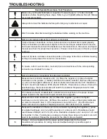
Deck System Resistance Test Procedure
Make sure your Digital Multimeter is capable of measuring up to 1.2 million ohms(Ω)
resistance before beginning these steps. Refer to your Digital Multimeter Owner's Manual
for correct dial settings.
Always disconnect the batteries before performing any maintenance or repair.
Wait 5 minutes after disconnecting the batteries before working on the machine.
1
Remove any debris build-up from all deck components.
2
Verify all power connections on deck motors and deck controller are torqued properly.
If loss connections are discovered, tighten to the correct torque values found in service
and repair manual. Reconnect the batteries per the instructions in the service and repair
manual and check for proper deck operation. If loose connections are not found, proceed
to step 3.
3
Label all (8) deck controller connection points on the edge of the deck controller housing
so they are easily viewed for correct re-connections.
4
To ensure correct re-connection, mark all (8) wire connections with the corresponding
connection point labels from step 3.
5
Remove all (8) wire connections from the deck controller.
6
Measure deck controller resistance (Ω) : (A) Place the negative (-) probe of a digital
multimeter on the positive (+) battery terminal of the deck controller. (B) Place the positive
(+) probe of the digital multimeter on deck controller terminals AR, then CR. Resistance
for each should read between 270K (Ω) and 330k (Ω). If resistance is above or below the
specified range, the deck controller will need to be replaced. Repeat process for deck
controller terminals AL, BL and CL.
7
If no issues are found, reinstall deck controller wire connections to the proper torque
values located in the service and repair manual. (See page 28)
8
Measure deck motor resistance (Ω): (A) Place the negative (-) probe of a digital
multimeter on motor terminal A. (B) Place the positive (+) probe of thed igital multimeter
on motor terminals B, then C. If the resistance is more than o to 1 (Ω )ohms the deck
motor will need to be replaced. Repeat process for other deck motor as needed.
9
Measure the resistance in the six-pin motor connector by placing the negative (-) probe
of a digital multimeter on pin 2 and the positive (+) probe on pin 3. Resistance should
read between 800k(Ω) and 1.2m (Ω) ohms. Resistance between pin 2 and pins 1,4,5 and
6 should be 0 ohms. If resistances are above or below these ranges, the deck motor will
need to be replaced. Repeat the process for the other motor as needed.
10
If steps 1-9 are completed and the issues persist, please refer to the mower
manufacturer's procedure for wiring harness troubleshooting for possible repair or
replacement.


