Greenline 33
57
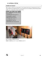
Inverter switch in ON position:
-
inverter on will be illuminated – 230V output. Maximal power consumption is limited to 3 kVA
(2.5kW).
-
12V batteries are being charged by VOLKSWAGEN alternator with up to 120 A and through 12V battery
charger (getting power from inverter).
SAILING WITH ELECTRIC MOTOR
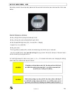
Electric motor is consuming up to 150 A on full throttle and appx. 50A at cruising speed, which is sufficient for
up to 4 hrs of sailing (flat seas, no wind). By switching ON the inverter, consumption of the electricity will rise
for cca. 30 A (depending on the consumers) -consequently the sailing range will drop.
During the electro propulsion, it is recommended that you reduce consumption of 230V consumers (normally
keeping on the fridge and 12 V charger only).
Inverter switch in ON position:
-
inverter on will be illuminated – 230V output. Maximal power consumption is limited to 3 kVA
(2.5kW).
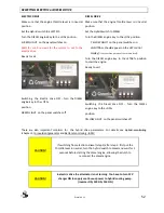
CAUTION!
When sailing in electric mode inverter should be turned ON to supply AC
power to battery charger to charge 12V batteries (also fuses F39 & F40
turned ON).
From 12V batteries important consumers are supplied which are
necessary for sailing: hybrid cooling pump, instruments, navigation
lights, etc...
IN THE MARINA
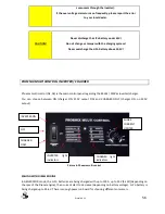
Assuming that the shore power cable is plugged in, the shore power fuse (under starboard cockpit seat – see
FUSE LOCATION) is turned ON and the inverter switch is turned to the ON position:
-
mains on is illuminated, bulk, absorption or float is illuminated (depending on charging phase)
-
with shore current limiter you can limit the current from the shore (in the case of weak shore fuses
you need to adjust the consumption to meet the shore supply). If you decrease it under the consumers
current, then the inverter will turn on (inverter on will illuminate)
-
if you turn the switch to Charger only, there won't be any 230V output, only the LiPo battery will be
charged.
-
if the shore current limiter is at 0A and the switch is in Charger only position, mains on will blink,
warning that there is no 230V output and there is no LiPo battery charging.
-
it is also recommended that the 230V fuse for the 12V battery charger is turned on, so that all 12V
batteries are being charged.
Содержание GREENLINE 33
Страница 1: ...OWNER S MANUAL GREENLINE 33 Revision 04 19 03 2012...
Страница 2: ...Greenline 33 II...
Страница 6: ...Greenline 33 VI Figure 38 Position of hoisting cradle and straps 88...
Страница 13: ...Greenline 33 6 Figure 1 Boat main dimensions...
Страница 16: ...Greenline 33 9 Figure 2 Boat examination report...
Страница 17: ...Greenline 33 10 Figure 3 Engine examination certificate VW SDI 75 5...
Страница 18: ...Greenline 33 11 Figure 4 Engine examination certificate VW TDI 165 5...
Страница 19: ...Greenline 33 12 Figure 5 Declaration of Conformity...
Страница 20: ...Greenline 33 13...
Страница 25: ...Greenline 33 18 MAN OVERBOARD PREVENTION AND RECOVERY Figure 8 Working deck area plan...
Страница 29: ...Greenline 33 22 FIGHT AGAINST FIRE EMERGENCY EXITS Figure 10 Fire extinguishers positions Emergency exits...
Страница 34: ...Greenline 33 27 Figure 14 Bilge pump system plan...
Страница 36: ...Greenline 33 29 4 HULL THROUGH HULL FITTINGS Figure 16 Thru hull fitting positions...
Страница 48: ...Greenline 33 41 7 PLUMBING Sea water plumbing Figure 22 Sea water plumbing...
Страница 49: ...Greenline 33 42 Freshwater plumbing Figure 23 Fresh water plumbing...
Страница 50: ...Greenline 33 43 Grey water plumbing Figure 24 Grey water plumbing...
Страница 58: ...Greenline 33 51 Picture 5 INVERTER switch Phoenix multi control on the dashboard...
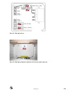
Страница 74: ...Greenline 33 67 Picture 13 Main 12V power box Picture 14 Service box fuses...
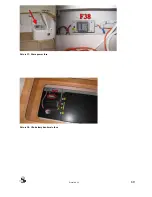
Страница 76: ...Greenline 33 69 Picture 17 Shore power fuse Picture 18 LiPo battery bank main fuse...
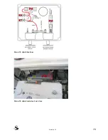
Страница 77: ...Greenline 33 70 Picture 19 Hybrid box fuses Picture 20 Hybrid control unit main fuse...
Страница 93: ...Greenline 33 86 In case of steering mechanism failure mount emergency steering tiller directly on rudder shaft...
Страница 95: ...Greenline 33 88 PO SITIO N O F HO ISTING C RADLE AND STRAPS Figure 38 Position of hoisting cradle and straps...
Страница 99: ...Greenline 33 92 UN MOUNTING LIPO BATTERY BANK 8 STEPS Picture 1 Step 1 Picture 2 Steps 2 7...
Страница 100: ...Greenline 33 93 Picture 3 Step 7 Picture 4 Step 8 Step 1...
Страница 102: ...Greenline 33 95 12 APPENDIX A Wiring diagrams...
Страница 108: ...Greenline 33 101 14 NOTES...
Страница 109: ...Greenline 33 102...
Страница 110: ...Greenline 33 103...


