GREAT PLANES ULTRA SPORT 60 Скачать руководство пользователя страница 4

DECISIONS YOU MUST MAKE NOW

ENGINE AND MOUNT SELECTION

The recommended engine size range is as follows:

.60 - .65 cubic inch displacement 2-cycle
.70 - .91 cubic inch displacement 4-cycle

The engine you select will determine how you build the

fuselage, so it is important that you have the engine close at
hand while building.

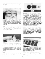
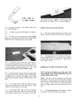
This kit includes the new Great Planes Adjustable

Engine mount. This mount will work on most .40-.60
2-Cycles and .40-.70 4-cycles. Cut or break the

"spreader bar" off each mount half. The surfaces

where the spreader bars were attached need to be
very smooth to allow the mount halves to fit together.
Snap the two mount halves together. Slide the mount
halves apart until the engine mounting lugs will sit
flat on the beams.

NOTE: If you choose to power your Ultra Sport 60 with a 4.
cycle engine, keep in mind that the RPM of your engine will
be considerably less than that of a 2-cycle engine; therefore,

you should select a higher pitch propeller to keep the speed
and overall performance roughly equivalent to that of a 2-
cycle engine. For example, an 11x7 or 11x8 prop would be
used with a .61 (2-cycle) engine; but an 11x11 prop may be
the best choice for a .91 4-cycle engine.

LANDING GEAR CONFIGURATION

The Ultra Sport 60 may be built with a "taildragger"

or "tricycle" landing gear configuration, and a retractable
main
 gear may be installed if you want to really ' 'clean up"
this airplane for ultra-smooth and precise aerobatics.

There is not. however, room for a nose gear retract;

therefore, if you want retracts, you'll have to use the "tail-
dragger" configuration.

OTHER ITEMS REQUIRED

• Four-channel radio with 4 servos (additional channel and

retract servo required if retracts are being used).

• Propellers (see engine instructions and above engine

notes for recommended sizes).

• Spinner (2-3/4" diameter)
• Fuel Tank (11 to 14 ounce)
• Main Wheels* - 2 (2-1/2" dia. for fixed gear and retract)
• Nose Wheel* - 1 (2-1/2" diameter, required for trike

only)

• Tail Wheel - 1 (1" diameter, required for taildragger

only)

• 5/32" Wheel Collars - 4 or 6
• 3/32" Wheel Collars - 2 (required for taildragger only)
• Iron-on Covering Material
• Silicone Fuel Tubing
• Wing Sealing Tape (or silicone sealer ... see instruc-

tions)

• Latex Foam Rubber Padding (1/4" thick)
• Dubro "E-Z Connectors" (or equivalent) - 2
• Main Gear Retracts: (optional)

Mechanical: Dave Brown 2-Gear Main, or

equivalent

Pneumatic: Robart #605 90-degree mains, or

equivalent (requires #188 air control kit)

• Plastic Pilot (Williams Bros. 2-5/8" scale)

•"Lightweight wheels are recommended.

SUPPLIES AND TOOLS NEEDED

2 oz. Thin CA Adhesive
2 oz. Medium or Thick CA Adhesive
2.5 oz. 30-Minute Epoxy
Hand or Electric Drill
Drill Bits: 1/16". 5/64", 3/32", 7/64", 1/8", 9/64". 5/32",

13/64", 7/32". and 1/4"

Sealing Iron
Heat Gun
Hobby Saw (Xacto Razor Saw)
Xacto Knife, #11 Blades
Pliers
Screw Drivers
T-Pins
Straightedge
Masking Tape
Sandpaper (coarse, medium, fine grit)*

T-Bar Sanding Block, or similar
Waxed Paper
Lightweight Balsa Filler

1/4-20 Tap, Tap Wrench

Vaseline Petroleum Jelly
Isopropyi Rubbing Alcohol (70%)
3M "77" Spray Adhesive (optional)
Dremel Moto Tool or similar (optional)

*NOTE: On our workbench, we have four 11" T-Bar

sanders, equipped with #50, #80, #100 and #150-grit sandpa-
per. This setup is all that is required for almost any sanding
task. We also keep some #320-grit wet-or-dry sandpaper
handy for finish sanding before covering.

4

Содержание ULTRA SPORT 60

Страница 1: ...shrods etc and to test the model and fly it only with experienced competent help using common sense and in accordance with all safety standards as set down in the Academy of Model Aeronautics Safety C...

Страница 2: ...Tubes 22 Mount the Wing to the Fuse 23 Fit Fuel Tank Fuelproofing 25 Install Turtle Deck 25 Assemble Nose Section 27 FINAL ASSEMBLY 30 Sand Fuselage 30 Install Wing Fairings 30 Install Wing Fillets 3...

Страница 3: ...Sport 60 is an excellent choice 4 You mustproperly install allR C and othercomponents so that the model operates properly on the ground and in the air 5 You must test theoperation ofthe model before t...

Страница 4: ...dragger configuration OTHER ITEMS REQUIRED Four channel radio with 4 servos additional channel and retract servo required if retracts are being used Propellers see engine instructions and above engine...

Страница 5: ...5 DIE DRAWINGS Use this drawing to help you identify the die cut parts...

Страница 6: ...block sand both sides of the fin smooth Then sand the leading edge and top edge to a rounded shape as shown on the plan Draw a centerline along the trailing edge of the fin to mark the hinge line 5 G...

Страница 7: ...the 1 8 wire elevator joiner 2 Glue the stab front to the stab rear Then glue on the stab tips Sand the frontofthe stab tips to blend with the stab 3 Glue the elevator ends to the elevators and sand t...

Страница 8: ...e the slot it in using 5 minute or 30 minute epoxy Work plenty of epoxy into the holes with a toothpick then lay the elevator leading edges along a straightedge to insure perfect align ment by folding...

Страница 9: ...t side ofthe ribs as shown on the plan make a right and a left set Sand the doublers even with the edge of the ribs 8 Prepare the leadingedgesheeting as follows Edge glue the 3 32 x 1 x 13 balsa sheet...

Страница 10: ...lied NOTE The narrow end of the TE jig is at rib W ll Pin the jig to the building surface all ribs are inserted into the LE notches Angle rib W l slightly using the dihedral gauge DG Glue W 1 to the T...

Страница 11: ...a wet cloth masking tape and T pins Read through the following step and go through a dry run before actually gluing 24 Position the leading edge sheeting at the rear edge of the notched LE so there is...

Страница 12: ...plan out your installation the LG block and to the 1 16 ply doubler on rib W 2 as shown on the plan and in the photo then epoxy the small hardwood block to the other end of the LG block and to the 1...

Страница 13: ...f the 1 16 ply dihedral brace Slide the dihedral brace in place push the wing panels together and immediately proceed to the next step 35 Now go back and repeat Steps 9 through 34 to build 4 With the...

Страница 14: ...The torque rod horns must exit the TOP of the wing FIBERGLASS THE CENTER SECTION 6 Slide the plastic bearings toward the threaded end of the torque rods then use a toothpick to apply a small amount o...

Страница 15: ...spray adhesive should hold the cloth down to the surface but will permit you to lift and reposition the cloth if you make a mistake Keep working forward along the top of the wing around the leading ed...

Страница 16: ...g edge of the ailerons to the same 1 Draw an accurate centerline along the LE of the tapered balsa ailerons and the wing TE 2 Check the length of your ailerons against the actual 10 Insert the hinges...

Страница 17: ...webs NOTE Try to drill straight in 5 Sand one end of each wing dowel to a rounded or pointed shape This is the end that will be inserted Do not sand the other end at this time notched LG blocks and sa...

Страница 18: ...retracts making sure they operate freely and reliably Also make sure 2 Carefully position the die cut 3 16 balsa lower front fuse side so the rear edge lines up with the front of the wing saddle open...

Страница 19: ...o the aft end ofone of the fuse sides and sand it even with the top and bottom edges 6 Find the two die cut 1 8 ply fuselage doublers and 10 From the 1 4 balsa triangle cut pieces to fit be 7 Edge glu...

Страница 20: ...installed perpendicular to the building surface 8 Once you have everything fitting properly re as semble the above parts using clamps pins tape and weights toholdeverything togetherand flaton the work...

Страница 21: ...it to make sure it will fit correctly before proceeding to the next step 14 Before installing the firewall F l you may drill F l for your engine mountand install the 6 32 blind nuts You may cut out th...

Страница 22: ...rmers F 6 F 5 and F 4 1 inch high 2 Trim the 3 16 x 1 2 x 3 5 8 ply servo rails to fit between the fuse side doublers in the locations shown on the plan Temporarily mount your servos to the rails then...

Страница 23: ...es flush with the front of F l 13 Cut the pushrod wires supplied to the required lengths and temporarily install the throttle and nose gear pushrods NOTE A 34 wire threaded one end is supplied for the...

Страница 24: ...els for easier insertion into F 2A Mix up a batch of 30 minute epoxy use a long stick to work some epoxy into the dowel holes smear epoxy on the dowels then re insert the dowels into the wing leaving...

Страница 25: ...ll the tank be sure tocushion itfrom vibration and prevent it from moving by surrounding the tank on all sides and front with latex foam rubber Leave a few inches ofextra fuel tubing in front of F l y...

Страница 26: ...around the formers and onto the stringers HINT This requires about 5 sets of hands so use several long pieces of masking tape to pull the sheering together then working a small section at a time add C...

Страница 27: ...ine from the centerline of F 3A to F 6A 1 Find the 1 4 x 1 4 x 10 balsa cockpit sides Cut offone end ofeach stick at an angle to fit the front edge of the backrest F 3A 2 Glue the cockpit sides to the...

Отзывы: