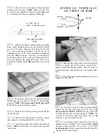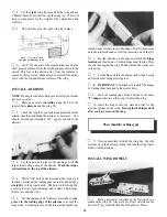
12. Find the 1/4" ply wing hold-down block and trial fit
15. Use 30-minute or 5-minute epoxy to securely glue
it into the notches in the fuse side doublers, sanding as
necessary for a good fit. Glue the hold-down block in place
securely, using 30-minutc epoxy, then cut pieces of 1/4"
balsa triangle and glue them in place above and below the
hold-down block. Sand the triangles flush with the wing
saddle.
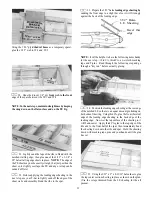
F-l to the fuse sides, holding with clamps or tape until the
glue has firmly set. NOTE: Before the glue sets. double
check to make sure F-1 is properly aligned with the top and
bottom edges of the fuselage, and fully back against the
firewall spacers. After the glue has fully hardened, sand off
the front of the fuse sides flush with the front of F-l.
13. The 1/4" ply firewall (F-l) location and size will
vary, depending on which engine you install. The location
has been set by the firewall spacers. The firewall supplied in
your kit is the correct size if you are installing a .91 4-stroke
engine; however, if you are installing a smaller engine, such
as a .70 4-stroke or a .61 2-stroke, you will have to cut the
firewall down to the correct size. The fuse plan shows the
firewall sizes and engine mounting required for the three
locations. Cut the firewall to size and sand the sides and
bottom at an angle to match the fuse. Trial fit to make sure it
will fit correctly before proceeding to the next step.
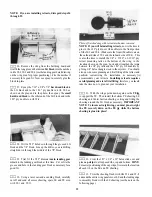
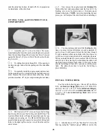
14. Before installing the firewall (F-l), you may drill
F-l for your engine mountand install the 6-32 blind nuts. You
may cut out the appropriate F-l drawing from the plans, tape
it to F-l and use it as a guide for drilling the four 5/32" holes.
If you will be using a mount not shown on the plans you'll
have to determine the correct mounting position. Note that
the mount should not be positioned on the vertical and
horizontal centerlines of F-1, but should be offset slightly
above the centerline and slightly toward the left side. (When
taking measurements off the plan, keep in mind that the plan
shows the bottom view of the airplane). Drill the holes and
install the blind nuts on the back ofF-1, pressing them in with
a pliers or a vise.
6-32
Blind Nut
21
#6 x 1" Screw
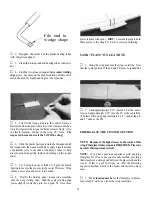
16. Cut pieces of 3/8" balsa triangle to fit around the aft
edges of F-1, and glue them in place.
DRILL ENGINE MOUNT
(Great Planes MM60L mount)
1. Place the engine pointing straight ahead on the
mount and mark the mounting hole locations on the mount.
At the marked locations, accurately drill 7/64" (or #36) holes.
NOTE: If you have access to a drill press, use it for drilling
these holes to insure that they are drilled vertically.
2. Now you may use one of the following methods to
attach your engine to the mount:
Method 1: Screw the #6 x 1" sheet metal screws
(provided in the kit) through the engine mounting flange and
into the mount. When first installing these screws, put a drop
of oil into each screw hole.


