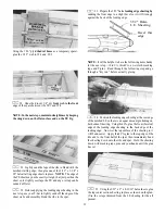
sand the entire fuse bottom, forward ofF-2A, in preparation
for installation of the chin block.
5. Now remove the engine mount and fuelproof the
inside of the fuel tank compartment and the front of F-l by
brushing on a coat of polyester resin or 30-minute epoxy
thinned with alcohol. NOTE: Later when installing the nose
pieces, you will fuelproof the chin block before installing it.
FIT FUEL TANK and FUELPROOF TANK
COMPARTMENT
6. You may permanently install the fuel tank at this
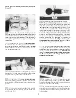
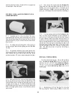
1. Assemble your 11 to 14 oz. fuel tank. Werecom-
mend bending the brass tubes as shown in the photo to prevent
them from cutting through the silicone fuel lines if pressed
against the firewall. (Try not to' 'kink'' the tubes when bend-
ing, however).
2. Try sliding the tank in through F-2. If the opening is
not large enough, sand or file the opening until the tank slides
in easily.
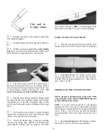
time, or you may wait until the plane is nearly completed. If
you do it now it will be easier to feed the fuel lines through
F-1, and to make sure there are no kinks in the lines; however,
you'll have to work around them while completing the nose.
When you install the tank, be sure to cushion it from vibration
and prevent it from moving by surrounding the tank on all
sides (and front) with latex foam rubber. Leave a few inches
of extra fuel tubing in front of F-l (you can cut off the excess
later). The photo shows how to route the fuel tubing to
prevent kinking.
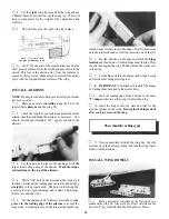
3. Temporarily install the engine mount and note how
far the mounting screws protrude into the fuel tank compart-
ment. Remove the screws and cut them off so they do not
protrude more than 1/8" (to prevent puncturing the fuel tank).
4. Drill two holes (7/32" or size to fit your fuel tubing)
near the top of F-l for your fuel tubing vent and fill lines. The
location of these holes will depend somewhat upon the type
of engine you are using, etc. It is OK to drill the holes in the
upper left and upper right comers, but we prefer drilling both
holes in the upper right comer (as viewed from the rear) for
easier access.
INSTALL TURTLE DECK
You'll need the following pans: Die-cut 1/8" ply F-3A,
F-4A. and Backrest Gauge (BG); die-cut 1/8" balsa F-5A
and F-6A; two 1/4" x 1/4" x 27" balsa turtle deck stringers;
two 3/32" x 3-1/4" x 28-1/4" balsa turtle deck sides; the 1/2"
x 2-3/8" x 26" balsa turtle deck top block and a roll of
masking tape.
1. Glue the die-cut 1/8" ply "backrest" (F-3A) to the
fuse top, using the "backrest gauge" (BG) to set it at the
25

