❏
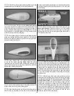
6. Disconnect the clevises from the control horns. Make
a 90° bend at the marks you made. Temporarily install a
nylon Faslink
™
on each pushrod and cut the wire so it
slightly protrudes out of the Faslink. Hint: If you prefer to
bend and cut the pushrods out of the fuselage, remove the
clevis, pull the pushrod out, make the 90° bends at the
marks and cut the rods. Reinstall the pushrods in the pushrod
tubes from the front and screw the clevises back on.
Note: If necessary, enlarge the holes in the servo arms with
a 5/64" [1.9mm] drill bit (or a #48 drill for precision).
❏ ❏
1. Remove the aileron servo hatch from one of the
wing halves. Position the servo on the hatch so that the
servo arm is centered in the hatch opening. From the 1/4" x
3/8" x 6" [6.4mm x 9.5mm x 152.4mm] basswood stick, cut
two servo mounting blocks 1/2" [12.7mm] long. Use 30-minute
epoxy to glue the servo mounting blocks to the servo hatch.
Note: Secure the servo mounting blocks by first drilling
several 1/16" [1.6mm] holes about 1/8" [3.2mm] deep into
the gluing surface of the basswood blocks. Roughen the
servo hatch where the epoxy will be applied. Pack epoxy
into the 1/16" [1.6mm] holes before clamping the blocks into
position.
❏ ❏
2. After the epoxy has fully cured, insert a 1/32" [.8mm]
temporary shim between the servo and the plywood hatch.
Drill 1/16" [1.6mm] pilot holes and mount the servos to the
mounting blocks using the hardware that came with the
servos. Remove the shims.
❏ ❏
3. Trim a servo arm so that only one arm remains.
Install the servo arm on the servo and reinstall the hatch in
the wing.
❏ ❏
4. Connect a 12" [304.8mm] servo extension to the
aileron servo. Cut a small exit hole for the servo wires in the
top wing sheeting, at the center of the wing. Route the servo
wires through the wing and out the exit hole.
❏ ❏
5. Thread a nylon clevis 14 turns onto a 2-56 x 4"
[101.6mm] wire pushrod. Attach the clevis to a small nylon
control horn. Position the control horn on the aileron control
horn mount. With the pushrod aligned with the servo horn,
mark the control horn mounting holes.
❏ ❏
6. Drill a 1/16" [1.6mm] pilot hole at each mark. Attach
the control horn with two #2 x 3/8" [9.5mm] sheet metal
screws. Remove the screws and harden the screw holes
with a drop of thin CA. After the CA has cured, reinstall the
horn and screws.
Install the Aileron Pushrods
34
Содержание Ryan STA EP
Страница 7: ...7 DIE CUT PATTERNS...
Страница 48: ...TWO VIEW DRAWING Use copies of this page to plan your trim scheme...
Страница 49: ...B C...
Страница 50: ...D A...


