❏
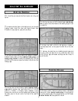
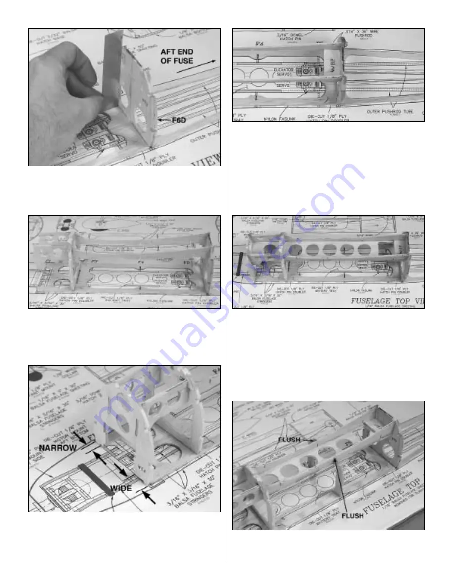
7. Glue former F6A perpendicular to the fuselage base
with formers F6D towards the aft end of the fuselage.
❏
8. Glue the two die-cut 3-ply wing saddles between
formers F2A and F6A. Make sure the wing saddles are fully
seated in the slots.
❏
9. Glue the die-cut 3-ply former F1A to the front of the
wing saddle and the fuselage base. Make sure the
embossed
F1A faces forward. Note: The front of the wing
saddle will provide approximately 2 degrees of down thrust
when the motor is installed.
❏
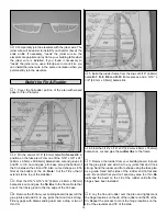
10. Glue the die-cut 3-ply wing bolt plate (WBP) to the
wing saddle and former F6A.
❏ ❏
11. Glue the die-cut 3-ply battery tray to the top of the
wing saddle and formers F1A, F2A and F3A.
❏
12. Glue the die-cut 3/32" [2.4mm] balsa formers F4A to
the wing saddle and the fuselage base. The former should
be flush with the bottom of the wing saddle.
21
Содержание Ryan STA EP
Страница 7: ...7 DIE CUT PATTERNS...
Страница 48: ...TWO VIEW DRAWING Use copies of this page to plan your trim scheme...
Страница 49: ...B C...
Страница 50: ...D A...


