


❏
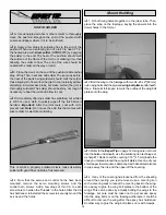
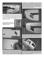
2. Stick a T-pin through the middle of all the hinges. Insert
four hinges into the hinge slots of each wing.
❏
3. Without using any glue, join the ailerons to the wings
and take out the T-pins. Make sure there is a small gap
between the leading edge of each aileron and the wing-just
enough to see light through or to slip a piece of paper through.
❏
4. Apply at least eight drops of thin CA to the top and
bottom of all the hinges. Allow enough time between each drop
so the CA can soak into the hinge rather than running into the
hinge gap. Hint: CA applicator tips are highly recommended.
Do NOT use accelerator!
❏
5. After the CA has hardened for a few minutes, pull hard
on each aileron to make sure all the hinges are secure. Add
more CA if necessary.
❏
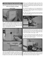
1. Connect a 12" [300 mm] servo extension wire to each
aileron servo. Cut one of the pieces of the supplied heat
shrink tubing in half and use each piece to secure each
servo connection.
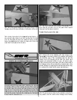
Refer to this photo while mounting the servos
and hooking up the ailerons.
❏
2. Use the string in the wings to pull the servo wires out
and place the servos in the openings. With the servos in the
wing, drill 1/16" [1.6 mm] holes for all the servo mounting
screws. Temporarily mount the servos with the screws that
came with the servos.
❏
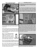
3. Read the Expert Tip that follows on how to solder.
Connect the aileron servos to the ailerons using the hardware
shown in the photo. The servo arms should be opposed as
shown in the sketches. When mounting the control horns,
place the front of the horn at the front of the aileron as
indicated by the arrow. Drill 3/32" [2.4 mm] holes into the
aileron for the screws. Do not cut the extra arms off the servo
arms until instructed to do so when setting up the radio later.
Note: Screw the 4-40 clevis onto the pushrod twenty full turns.
CONTROL HORN
Mount the Servos & Hook Up the Ailerons
9
Содержание Giant Super Sportster
Страница 32: ......


