GREAT PLANES Giant Super Sportster Скачать руководство пользователя страница 19

(Remember, “Gas-only” steps are shaded.)

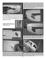
1. This step is necessary only if using a gas engine.

If using a glow engine, proceed to step 2. Use coarse
sandpaper to roughen the firewall for the cowl mounting
blocks. Use 30-minute epoxy to glue both hardwood cowl
mounting blocks into position where shown. (The cowl
blocks are necessary for gas engine installation because the
Fuji 32–and probably most other gas engines–protrude
farther than the 7-1/4" [185 mm] specified for glow engines.
This means the cowl will also be farther forward, so without
the cowl mounting blocks the cowl mounting screws would
be too close to the aft edge of the cowl.)

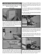
Refer to this photo for Steps 2 and 

3

.

2. Place the cowl on the fuselage over the engine and

temporarily mount the spinner back plate and prop. Align the
front of the cowl with the spinner back plate, with
approximately 1/8" [3 mm] spacing between them. Hint: If
mounting the Fuji 32, temporarily remove the carburetor and
spark plug so the cowl will fit.

3. Holding the cowl in position, use a fine-point felt-tip

pen to draw the outline of the cowl directly onto the fuselage.
Remove the propeller, back plate and cowl.

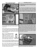
Refer to this photo both for Steps 4A and 4B.

4A. Glow Engines: Using the line around the fuselage

as a reference to take measurements from, drill six 1/8" 
[3.2 mm] holes in the sides and top of the cowl so they will
be 3/16" [5 mm] behind the front edge of the firewall–this will
center the screws in the firewall.

4B. Gas Engines: Using the line around the fuselage as a

reference to take measurements from, drill six 1/8" [3.2 mm]
holes in the sides and top of the cowl. The two top holes
should be positioned so the screws will be centered in the
cowl mounting blocks and the holes in the sides of the cowl
should be approximately 3/8" [10 mm] aft of the front edge of
the side tabs.

5. Reposition the cowl on the fuselage. Mount the spinner

back plate and prop.

6. Again holding the cowl in position (it may be helpful to

have an assistant), drill a 3/32" [2.4 mm] hole into the
fuselage through one of the cowl holes. Mount the cowl to
the fuselage with one #4 x 5/8" [16 mm] Phillips screw into
the hole you just drilled.

Perform step 4A only if you have mounted a glow engine.
Perform step 4B only if you have mounted a gas engine.
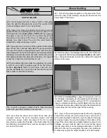
Mount the Cowl

19

Содержание Giant Super Sportster

Страница 1: ...and unused condition to the place of purchase To make a warranty claim send the defective part or item to Hobby Services at the address below Hobby Services 3002 N Apollo Dr Suite 1 Champaign IL 61822...

Страница 2: ...your stable for a long time Powered by a 1 60 two stroke the Super Sportster handles just like a hot 60 size plane with the stability and presence of a giant scale model Powered by a Fuji Imvac 32 th...

Страница 3: ...d the work area thoroughly after working with fiberglass parts Remember Take your time and follow the instructions to end up with a well built model that is straight and true This is a partial list of...

Страница 4: ...3 1 4 Great Planes plastic spinner with an aluminum back plate could be used instead of the included aluminum spinner This setup requires no adapter kit because the cone is mounted to the back plate w...

Страница 5: ...greatplanes com and click on Technical Data Due to manufacturing tolerances which will have little or no effect on the way your model will fly please expect slight deviations between your model and t...

Страница 6: ...heel collar 1 1 25 mm tail wheel 1 2 56 x 1 25 mm threaded rod for gas throttle pushrod 1 2 56 x 36 910 mm pushrod glow throttle pushrod 1 1 4 20 blind nuts in fuselage 2 Metric fasteners for mounting...

Страница 7: ...servos as shown in the sketch Also cut the covering from the 1 4 6 5 mm wing bolt holes from the slots for the main landing gear wires and from the holes for the servo wires in the top of both wings n...

Страница 8: ...x 1 3 4 10 x 45 mm hardwood wing dowels Use epoxy to glue in both dowels so 7 16 10 mm of each dowel protrudes 9 Use epoxy to glue the 1 4 x 1 1 4 6 x 30 mm hardwood alignment dowel halfway into one...

Страница 9: ...the pieces of the supplied heat shrink tubing in half and use each piece to secure each servo connection Refer to this photo while mounting the servos and hooking up the ailerons 2 Use the string in...

Страница 10: ...4 Now that the servos and control horns have been mounted remove the servo mounting screws and the control horn screws Add a few drops of thin CA to each screw hole to harden the threads in the holes...

Страница 11: ...ing turn the fuselage upright Take accurate measurements to center the trailing edge of the stab laterally Insert T pins into both sides of the trailing edge next to the fuselage to hold the alignment...

Страница 12: ...rn into the wood The hotter the soldering iron the faster it must travel to melt a fine cut 7 Peel the covering from the middle of the stabilizer Then wipe away the ink with a few of your paper towel...

Страница 13: ...he ailerons except use 4 40 x 3 4 19 mm Phillips screws and the mounting plates on the other side of the control surfaces for mounting the horns When mounting the horns locate the clevis holes over th...

Страница 14: ...e the 8 32 screw and washers to draw it the rest of the way in 3 Mount the engine mount to the firewall with four 8 32 x 1 1 4 32 mm socket head cap screws SHCS and 8 flat washers and lock washers but...

Страница 15: ...the servo and harden the holes with a few drops of thin CA and then remount the servo Glue in the throttle pushrod guide tube with CA GAS ENGINE FUJI BT 32 If mounting a gas engine other than the Fuj...

Страница 16: ...tray with the screws that came with the servo Remove the servo and harden the holes with a few drops of thin CA Then remount the servo Glue in the guide tube with CA MOUNT THE KILL SWITCH FOR SPARK IG...

Страница 17: ...bes and metal plates Solder another fuel line barb onto the ends of the short tubes Bend the brass vent overflow tube upward so it will be at the top of the tank 3 Connect the fuel tubing to the short...

Страница 18: ...through and then insert the plastic fueling plug and press the end of the line back into the collar Note Do not mount the fuel tank in the aft mounting location for glow engine use Most glow engines...

Страница 19: ...tip pen to draw the outline of the cowl directly onto the fuselage Remove the propeller back plate and cowl Refer to this photo both for Steps 4A and 4B 4A Glow Engines Using the line around the fuse...

Страница 20: ...cutout air cooling inlet and spark plug clearance has been provided in the back of the manual Starting with the carburetor cut out the template and then transfer the cutout to a piece of thin cardboa...

Страница 21: ...in the plywood disc on the other side of the pant 4 With the plane sitting on its main wheels and tail wheel use a block of balsa or something similar to prop up one of the wheel pants 5 8 16 mm 5 Fi...

Страница 22: ...rd locations for glow engines You could go ahead and mount the battery and receiver now or do a quick C G check first to find out where the battery should be mounted If you would like to do a quick C...

Страница 23: ...hown is the one included with the Great Planes Super Stearman ARF and is also available separately GPMA2475 Trim down the base of the pilot so he will fit under the canopy For the most security cut a...

Страница 24: ...the servos Use a Great Planes AccuThrow or a ruler to accurately measure and set the control throw of each control surface as indicated in the chart that follows If your radio does not have dual rate...

Страница 25: ...nt as close to the firewall as possible Note If attaching weight to the firewall do not rely upon the adhesive on the back of the lead weight to permanently hold it in place Over time fuel and exhaust...

Страница 26: ...odel and while you work the controls tell you what the control surfaces are doing Repeat this test with the engine running at various speeds with an assistant holding the model using hand signals to s...

Страница 27: ...chnics any device that explodes burns or propels a projectile of any kind 1 I will have completed a successful radio equipment ground check before the first flight of a new or repaired model 2 I will...

Страница 28: ...nimums Batteries should be able to sustain power to the onboard radio components for a minimum of one hour total flying time before recharging Redundant and fail safe battery systems are recommended T...

Страница 29: ...the ground and make sure it tracks straight by doing a few practice runs at low speeds on the runway Hold up elevator to keep the tail wheel on the ground If necessary adjust the tail wheel so the mo...

Страница 30: ...irspeed 3 point landings are done with ease just continue to increase up elevator allowing the model to stall at the same time the main gear touches Once the model is on the runway hold up elevator to...

Страница 31: ...R 3 16 4 8 mm HOLES 1 2 1 8 GLOW ENGINE MOUNTING TEMPLATE CUT OUT ON DOTTED LINE AIR COOLING INLET TEMPLATE C A R B U R E T O R C U T O U T F O R F U J I B T 3 2 SPARK PLUG CUT OUT FOR FUJI BT 32 TEMP...

Страница 32: ......

Отзывы: