GREAT PLANES Giant Super Sportster Скачать руководство пользователя страница 29

1. Fuelproof all areas exposed to fuel or exhaust residue

such as the wing saddle area, the wing dowels, etc.

2. Check the C.G. according to the measurements

provided in the manual.

3. Be certain the battery and receiver are securely

mounted. Simply stuffing them into place with foam
rubber is not sufficient.

4. Extend your receiver antenna into the antenna tube

inside the fuselage.

5. Balance your model 

laterally as explained in

the instructions.

6. Use threadlocking compound to secure critical

fasteners such as the set screws on the wheel
collars, screws that hold the carburetor arm (if
applicable), screw-lock pushrod connectors, etc.

7. Add a drop of oil to the axles so the wheels will

turn freely.

8. Make sure all hinges are securely glued in place.

9. Reinforce holes for wood screws with thin CA where

appropriate (servo mounting screws, cowl mounting
screws, etc.).

10. Confirm that all controls operate in the correct direction

and the throws are set up according to the manual.

11. Make sure there are silicone retainers on all the

clevises and that all servo arms are secured to the
servos with the screws included with your radio.

12. Secure connections between servo wires and 

Y-connectors or servo extensions, and the
connection between your battery pack and the on/off
switch with vinyl tape, heat shrink tubing or special
clips suitable for that purpose.

13. Make sure the fuel lines are connected and are

not kinked.

14. Balance your propeller (and spare propellers).

15. Tighten the propeller nut and spinner.

16. Place your name, address, AMA number and

telephone number on or inside your model.

17. Cycle your receiver battery pack (if necessary) and

make sure it is fully charged.

18. If you wish to photograph your model, do so before

your first flight.

19. Range check your radio when you get to the flying field.

The Giant Super Sportster ARF is a great-flying model that
flies smoothly and predictably. It does not, however, possess
the self-recovery characteristics of a primary R/C trainer and
should be flown only by experienced R/C pilots.

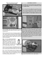
A fully-cowled engine may run at a higher temperature than
an un-cowled engine. For this reason, the fuel mixture
should be richened so the engine runs at about 200 rpm
below peak speed. By running the engine slightly rich, you
will help prevent dead-stick landings caused by overheating.

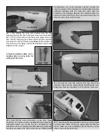
Before takeoff, see how the model handles on the ground
and make sure it tracks straight by doing a few practice runs
at low speeds on the runway. Hold “up” elevator to keep the
tail wheel on the ground. If necessary, adjust the tail wheel
so the model will roll straight. Top off the fuel, and then check
all fasteners and control linkages for peace of mind.

The Giant Sportster is an “honest” flier. Takeoff will be routine
straight forward–just remember to hold a bit of up elevator until
she gets up-to-speed to keep the tail on the ground. Get ready
to apply a little right rudder as the model gains speed and lifts
into the air. Be smooth on the controls and make a gentle
climbout to a safe altitude before making the first turn.

Takeoff

CAUTION (THIS APPLIES TO ALL R/C AIRPLANES): If,
while flying, you notice an alarming or unusual sound such
as a low-pitched “buzz,” this may indicate control surface
flutter. Flutter occurs when a control surface (such as an
aileron or elevator) or a flying surface (such as a wing or
stab) rapidly vibrates up and down (thus causing the noise).
In extreme cases, if not detected immediately, flutter can
actually cause the control surface to detach or the flying
surface to fail, thus causing loss of control followed by an
impending crash. The best thing to do when flutter is
detected is to slow the model immediately by reducing
power, then land as soon as safely possible. Identify which
surface fluttered (so the problem may be resolved) by
checking all the servo grommets for deterioration or signs of
vibration. Make certain all pushrod linkages are secure and
free of play. If it fluttered once, under similar circumstances
it will probably flutter again unless the problem is fixed.
Some things which can cause flutter are; Excessive hinge
gap; Not mounting control horns solidly; Poor fit of clevis pin
in horn; Side-play of wire pushrods caused by large bends;
Excessive free play in servo gears; Insecure servo
mounting; and one of the most prevalent causes of flutter;
Flying an over-powered model at excessive speeds.

Fuel Mixture Adjustments

FLYING

During the last few moments of preparation your mind may
be elsewhere anticipating the excitement of the first flight.
Because of this, you may be more likely to overlook certain
checks and procedures that should be performed before the
model is flown. To help avoid this, a check list is provided to
make sure these important areas are not overlooked. Many
are covered in the instruction manual, so where appropriate,
refer to the manual for complete instructions. Be sure to
check the items off as they are completed.

CHECK LIST

29

Содержание Giant Super Sportster

Страница 1: ...and unused condition to the place of purchase To make a warranty claim send the defective part or item to Hobby Services at the address below Hobby Services 3002 N Apollo Dr Suite 1 Champaign IL 61822...

Страница 2: ...your stable for a long time Powered by a 1 60 two stroke the Super Sportster handles just like a hot 60 size plane with the stability and presence of a giant scale model Powered by a Fuji Imvac 32 th...

Страница 3: ...d the work area thoroughly after working with fiberglass parts Remember Take your time and follow the instructions to end up with a well built model that is straight and true This is a partial list of...

Страница 4: ...3 1 4 Great Planes plastic spinner with an aluminum back plate could be used instead of the included aluminum spinner This setup requires no adapter kit because the cone is mounted to the back plate w...

Страница 5: ...greatplanes com and click on Technical Data Due to manufacturing tolerances which will have little or no effect on the way your model will fly please expect slight deviations between your model and t...

Страница 6: ...heel collar 1 1 25 mm tail wheel 1 2 56 x 1 25 mm threaded rod for gas throttle pushrod 1 2 56 x 36 910 mm pushrod glow throttle pushrod 1 1 4 20 blind nuts in fuselage 2 Metric fasteners for mounting...

Страница 7: ...servos as shown in the sketch Also cut the covering from the 1 4 6 5 mm wing bolt holes from the slots for the main landing gear wires and from the holes for the servo wires in the top of both wings n...

Страница 8: ...x 1 3 4 10 x 45 mm hardwood wing dowels Use epoxy to glue in both dowels so 7 16 10 mm of each dowel protrudes 9 Use epoxy to glue the 1 4 x 1 1 4 6 x 30 mm hardwood alignment dowel halfway into one...

Страница 9: ...the pieces of the supplied heat shrink tubing in half and use each piece to secure each servo connection Refer to this photo while mounting the servos and hooking up the ailerons 2 Use the string in...

Страница 10: ...4 Now that the servos and control horns have been mounted remove the servo mounting screws and the control horn screws Add a few drops of thin CA to each screw hole to harden the threads in the holes...

Страница 11: ...ing turn the fuselage upright Take accurate measurements to center the trailing edge of the stab laterally Insert T pins into both sides of the trailing edge next to the fuselage to hold the alignment...

Страница 12: ...rn into the wood The hotter the soldering iron the faster it must travel to melt a fine cut 7 Peel the covering from the middle of the stabilizer Then wipe away the ink with a few of your paper towel...

Страница 13: ...he ailerons except use 4 40 x 3 4 19 mm Phillips screws and the mounting plates on the other side of the control surfaces for mounting the horns When mounting the horns locate the clevis holes over th...

Страница 14: ...e the 8 32 screw and washers to draw it the rest of the way in 3 Mount the engine mount to the firewall with four 8 32 x 1 1 4 32 mm socket head cap screws SHCS and 8 flat washers and lock washers but...

Страница 15: ...the servo and harden the holes with a few drops of thin CA and then remount the servo Glue in the throttle pushrod guide tube with CA GAS ENGINE FUJI BT 32 If mounting a gas engine other than the Fuj...

Страница 16: ...tray with the screws that came with the servo Remove the servo and harden the holes with a few drops of thin CA Then remount the servo Glue in the guide tube with CA MOUNT THE KILL SWITCH FOR SPARK IG...

Страница 17: ...bes and metal plates Solder another fuel line barb onto the ends of the short tubes Bend the brass vent overflow tube upward so it will be at the top of the tank 3 Connect the fuel tubing to the short...

Страница 18: ...through and then insert the plastic fueling plug and press the end of the line back into the collar Note Do not mount the fuel tank in the aft mounting location for glow engine use Most glow engines...

Страница 19: ...tip pen to draw the outline of the cowl directly onto the fuselage Remove the propeller back plate and cowl Refer to this photo both for Steps 4A and 4B 4A Glow Engines Using the line around the fuse...

Страница 20: ...cutout air cooling inlet and spark plug clearance has been provided in the back of the manual Starting with the carburetor cut out the template and then transfer the cutout to a piece of thin cardboa...

Страница 21: ...in the plywood disc on the other side of the pant 4 With the plane sitting on its main wheels and tail wheel use a block of balsa or something similar to prop up one of the wheel pants 5 8 16 mm 5 Fi...

Страница 22: ...rd locations for glow engines You could go ahead and mount the battery and receiver now or do a quick C G check first to find out where the battery should be mounted If you would like to do a quick C...

Страница 23: ...hown is the one included with the Great Planes Super Stearman ARF and is also available separately GPMA2475 Trim down the base of the pilot so he will fit under the canopy For the most security cut a...

Страница 24: ...the servos Use a Great Planes AccuThrow or a ruler to accurately measure and set the control throw of each control surface as indicated in the chart that follows If your radio does not have dual rate...

Страница 25: ...nt as close to the firewall as possible Note If attaching weight to the firewall do not rely upon the adhesive on the back of the lead weight to permanently hold it in place Over time fuel and exhaust...

Страница 26: ...odel and while you work the controls tell you what the control surfaces are doing Repeat this test with the engine running at various speeds with an assistant holding the model using hand signals to s...

Страница 27: ...chnics any device that explodes burns or propels a projectile of any kind 1 I will have completed a successful radio equipment ground check before the first flight of a new or repaired model 2 I will...

Страница 28: ...nimums Batteries should be able to sustain power to the onboard radio components for a minimum of one hour total flying time before recharging Redundant and fail safe battery systems are recommended T...

Страница 29: ...the ground and make sure it tracks straight by doing a few practice runs at low speeds on the runway Hold up elevator to keep the tail wheel on the ground If necessary adjust the tail wheel so the mo...

Страница 30: ...irspeed 3 point landings are done with ease just continue to increase up elevator allowing the model to stall at the same time the main gear touches Once the model is on the runway hold up elevator to...

Страница 31: ...R 3 16 4 8 mm HOLES 1 2 1 8 GLOW ENGINE MOUNTING TEMPLATE CUT OUT ON DOTTED LINE AIR COOLING INLET TEMPLATE C A R B U R E T O R C U T O U T F O R F U J I B T 3 2 SPARK PLUG CUT OUT FOR FUJI BT 32 TEMP...

Страница 32: ......

Отзывы: