❏
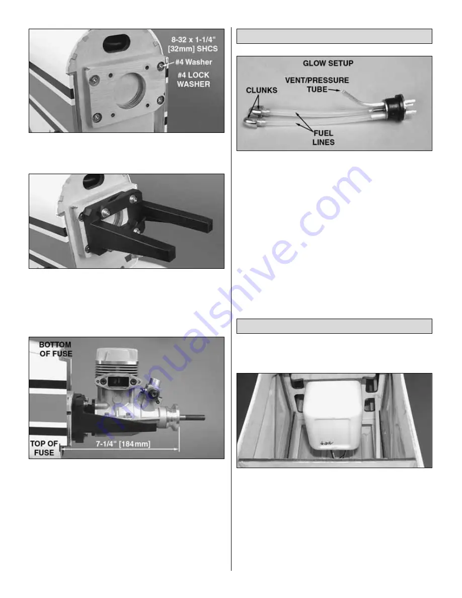
2. Attach the engine mount plate to the firewall using four
8-32 x 1-1/4" [32mm] SHCS, four #4 lock washers, and four
#4 flat washers.
❏
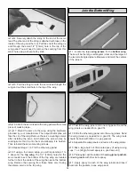
3. The glow engine will need to be mounted inverted, or
upside-down. Attach the black nylon engine mount to the
engine mount plate using four 8-32 x 1-1/4" [32mm] SHCS,
four #4 lock washers, and four #4 flat washers. Leave the
SHCS loose enough that you can adjust the width of the
mount as needed for your engine.
❏
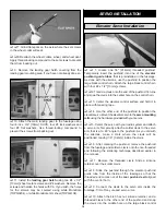
4. Position the engine on the mount so the distance from
the firewall to the front of the thrust washer measures 7-1/4"
[184mm]. Mark the location of the engine on the engine
mount. The Great Planes Dead Center
™
Hole Locator
(GPMR8130) works well for this. Drill through the marks you
have made on the engine mount with a #29 or 9/64" [3.6mm]
drill bit. Tap each of the holes with an 8-32 tap.
❏
5. Install the engine onto the mount with four each, 8-32
x 1" [25mm] SHCS, #8 flat washers and #8 lock washers.
❏
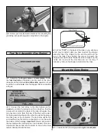
1. Assembly of the glow stopper is very similar to the gas
version. In place of brass tubing, you will use the hardware
pack including the silver colored aluminum tubes. Assemble
the stopper as shown in the photo. For the glow engine setup,
the vent line is connected to the pressure fitting on your
muffler. NO soldering or barbs are required for the glow setup.
❏
1. Cut three 12" [305mm] lengths of the appropriate type
of fuel line and connect them to the fuel tank.
❏
2. Insert the fuel tank into the fuselage. Route the fuel
lines through the circular cutout in the first former behind
the firewall.
❏
3. Guide the fuel lines toward the small oval opening in
the top of the firewall. Use a pair of long nose pliers to pull
the lines out of this opening. Slide the tank into place as you
pull the lines.
❏
4. The stopper assembly will fit into the circular cutout in
the former once the tank is fully seated.
Install the Fuel Tank
Fuel Tank Assembly (Glow Engine)
20


