GREAT PLANES FlyLite Скачать руководство пользователя страница 6

6

ASSEMBLY

Prepare the Fuselage

Your transmitter and a charged battery will be required 
soon for setting up the radio. If you plan to fl y your FlyLite 
immediately, charge your battery now so you will not have 
to wait later.

❏ 

1. Lift the back of the 

battery hatch

 to remove it from the 

fuselage—a little more force than usual may be required for 
the fi rst time as there may be some residual glue sticking the 
parts together. Use care. 

❏ 

2. There may be a small piece of tape temporarily stuck 

to the magnet on the hatch or to the magnet in the fuselage. 
Remove the tape and throw it away. Set the hatch aside.


❏ 

3. Lightly squeeze the main landing gear wire together 

and fi t it all the way up into the fuselage with the bent-in 
“sweep” in the wire facing forward.

❏ 

4. Apply the rougher, “hook” side of the included Velcro 

hook-and-loop strip to the battery mounting plate in the 
fuselage. Cut the softer, “loop” side of the Velcro strip into 
four pieces and attach one of the strips to your battery. If you 
already have more batteries you can apply the other strips to 
the batteries now. If you ever need more Velcro later, it can 
also be purchased separately (GPMQ4480).
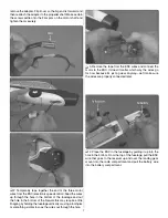
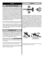
Mount the Motor

❏ 

1. Test fi t the included 8 x 6 Slow Flyer propeller onto the 

prop-saver propeller adapter on the RimFire 250 motor. If the 
propeller fi ts loosely, use a #0 or #1 Phillips screwdriver to 

Содержание FlyLite

Страница 1: ...y If the buyer is not prepared to accept the liability associated with the use of this product the buyer is advised to return this kit immediately in new and unused condition to the place of purchase...

Страница 2: ...please join The AMA is the governing body of model aviation and membership provides liability insurance coverage protects modelers rights and interests and is required to y at most R C sites The AMA h...

Страница 3: ...his system includes the R617FS receiver so if the smaller R6004FF receiver is preferred it will have to be purchased separately The 6EX has six model memory so even if it seems as though this system i...

Страница 4: ...ply a light mist of CA accelerator causing the CA to harden within seconds If you want to assemble a repair kit following are some recommended items UFO Thin foam safe CA HOTR1040 Great Planes Pro CA...

Страница 5: ...s 6 8x6 Power Flow Propeller 2 KIT INSPECTION Before starting to build inspect the parts to make sure they are of acceptable quality If any parts are missing or are not of acceptable quality or if you...

Страница 6: ...ow it away Set the hatch aside 3 Lightly squeeze the main landing gear wire together and t it all the way up into the fuselage with the bent in sweep in the wire facing forward 4 Apply the rougher hoo...

Страница 7: ...may require a little nagling by holding the fuselage vertically or using a toothpick or something similar to coax the wires out through the hole 3 Remove the tape from the ESC wires and connect the m...

Страница 8: ...turning the correct direction swap any two motor ESC wires with each other Con rm that the motor is now turning in the correct direction by advancing the throttle stick again 7 If your 0 Phillips scr...

Страница 9: ...drill or a hobby knife to carefully enlarge the holes just enough to t the micro screw lock connector Thread a 2mm x 4mm Phillips machine screw into each screw lock connector Use this photo for the n...

Страница 10: ...you do strip out the balsa the glue you added will hold the screws Hint If the servo arm is in the way of one of the screws turn on your radio and use the transmitter to rotate the servo arm to accom...

Страница 11: ...a 90 pushrod connector over the wire so it won t come off The connectors can also be installed removed after the plane is together but it s easier to do it now 5 Guide the pushrod wire up through the...

Страница 12: ...ge until it is snug and secure Note The n is held into position with built in magnets which also lock in the stab so no glue is required This is what the rudder pushrod tail wheel assembly looks like...

Страница 13: ...yLite outdoors rather than having the elevator centered it should have approximately 3 16 5mm of down trim This will allow your FlyLite to y level when ying at faster speeds typically used outdoors Ce...

Страница 14: ...y Place a ruler to the trailing edge of the elevator at the widest part from front to back 3 Use your transmitter to move the elevator up and measure the distance it moved from center This is your up...

Страница 15: ...ssively in large indoor sites where higher throttle settings may be used more often do not use the rubber band protectors Instead the formed wing center doubler and ber reinforced tape must be added t...

Страница 16: ...ng the C G lines in following steps Balance the Model C G Another critical factor in determining how a plane ies and again your ability to control it is the center of gravity C G or the balance point...

Страница 17: ...ightedge and a ne point felt tip pen to draw the C G range lines on the bottom of the wing connecting the sets of marks 5 If you still need to add the ber reinforced tape to the bottom of the wing for...

Страница 18: ...plane simply place segments of weight over the nose or on the tail to see how much is required Typically 1 4 oz to 1 2 oz 7g to 14g may be required on the nose while much less if any weight will be r...

Страница 19: ...ay use four rubber bands Always turn on the transmitter rst then connect the battery and install the hatch Do not arm the motor until you are actually ready to takeoff Always always always before each...

Страница 20: ...able to nd equilibrium with your FlyLite where it cruises slowly without climbing or descending Crossover If you re a beginner it might be best to start with a crossover pattern to avoid turning the p...

Страница 21: ...s when the plane is heading directly toward you Having the ability to y these different patterns and control the model in all orientations requires a little practice and dedication it s almost like ho...

Страница 22: ...nose down attitude 4 Level the wings applying elevator as necessary to control the descent If necessary apply throttle to stretch the approach to reach the landing zone Or apply throttle and go around...

Страница 23: ...ing 12 3 15 5 oz ft 38 47 g dm Length 31 5 in 800mm Great Planes PT 19 Parkflier EP ARF 41 5 GPMA1149 ALSO AVAILABLE FROM GREAT PLANES The Escapade is destined to become the plane you can t put down t...

Страница 24: ...ANCE RANGE 2 1 8 54mm from wing leading edge 2 7 8 73mm from wing leading edge Fold along this line Align with wing leading edge BALANCE RANGE 2 1 8 54mm from wing leading edge 2 7 8 73mm from wing le...

Отзывы: