


❏
4. Reinstall the rudder and make sure that the notch
allows proper clearance for the elevator joiner to operate
without binding when the rudder is fully deflected. Also, the
edges of the notch may need to be beveled to allow for full
movement of the rudder. Once you are satisfied that there
is no binding, glue the hinges using the same technique as
the elevator hinges.
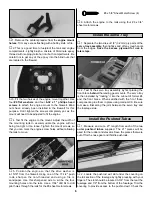
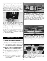
REFER TO THIS PHOTO FOR THE FOLLOWING 3 STEPS
❏
1. Locate the groove for the main landing gear under
the covering in the center of the fuselage by lightly
pressing with your finger. Using a hobby knife, carefully
remove the covering, exposing the groove.
Note: Do not cut into the wood around the groove.
❏
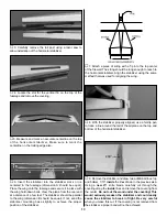
2. Carve a slight bevel on the
inside
edge of both holes.
This is to allow for the radius at the bend in the landing gear.
❏
3. To prevent fuel from damaging the exposed wood, a
thin coat of thin CA should be applied. This can be done by
applying the CA, then using a piece of waxed paper or
plastic, spread the glue until the wood has been completely
covered by the CA.
❏
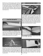
4. Measure in 1" from the outside edges of the fuselage
at the landing gear groove to locate the position of the
landing gear straps. Drill a 1/16" hole 3/32" from the
rear
edge
only at this time.
❏
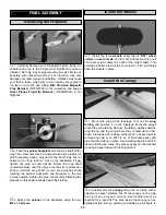
5. Install the
main landing gear
into position. Install the
landing gear straps
using two of the
#2 x 3/8"
screws.
Note
:Do not tighten the screws yet.
❏
6. Using the holes in the front of the straps as a guide,
drill a 1/16" hole for the front screws.
❏
7. Install the last two #2 x 3/8” screws. Remove all four
screws and harden the holes using two or three drops of thin
CA in each hole. After the CA has has time to cure, reinstall
the screws, making sure they are tightened completely.
❏
1. Insert a 5/32" wheel collar (without a screw) into the
nylon steering arm. Be sure that the set screw holes on
Mount the Nose Gear
Mount the Main Landing Gear
INSTALL THE LANDING GEAR
15


