GRAUPNER GmbH & Co. KG D-73230 KIRCHHEIM/TECK GERMANY
Modifications reserved. No liability for printing errors 11/2010
18
Fit the fueltank in the tank compartment working from the wing saddle, passing the
three fuel lines through the hole in the firewall. Glue a piece of scrap wood behind the
tank to prevent it shifting in flight.
Be sure to use the correct grade of fuel tubing, as different types are required for
petrol engines and glow engines.
The fuel tube connected to the clunk should be connected to the engine’s
carburettor, while the overflow should run down and out of the model. The fuel filler
line can later be routed out of the model through a hole in the cowl; it should be
sealed with a plug once the fueltank is full.
Installing the engine
Four holes have to be drilled in the firewall to accept the rubber damping elements;
the hole positions are specific to the engine you intend to fit.
We recommend that you remove the tailplane or tail assembly before installing the
power plant.
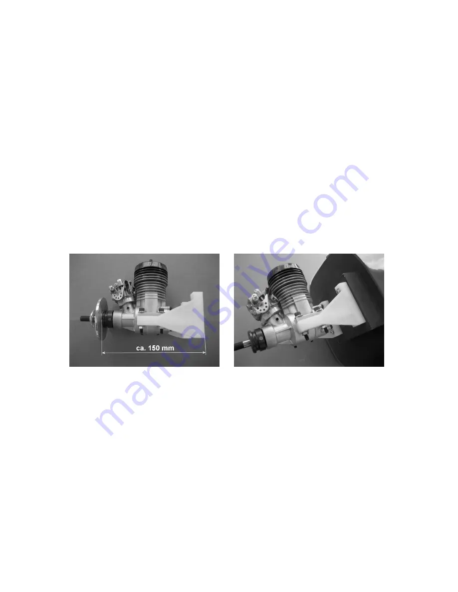
Position the engine on the arms of the engine mount in such a way that the distance
between the rear face of the mount and the front of the prop driver is around 150 mm.
You will find two reference lines marked on the firewall: one vertical, one horizontal.
The point where these two lines cross indicates the centreline of the engine. Mark the
position of the engine mount screw-holes on the firewall, and drill holes at the marked
points to accept the captive nuts.
Ensure that the engine can be attached to the
firewall in such a way that the silencer is positioned on the fuselage centreline;
this will require that the cylinder head be angled down by around 45°.
Fix the
engine mount to the firewall using the screws supplied with the unit, and apply UHU
thread-lock fluid to prevent the screws working loose.
If you intend to install an MVVS 40, it should be attached to the firewall using the
engine mount, Order No. 2781.300.


