GRAUPNER GmbH & Co. KG D-73230 KIRCHHEIM/TECK GERMANY
No liability for printing errors. Technnical modifications reserved.
#0060384
04/2009
47
positioned correctly relative to the lift, it is very likely that it will not be captured successfully. For this
reason it is important to practise the procedure so that you are able to position the daughter boat as
required.
TIP:
we recommend that the daughter boat should be drawn up with the motor running, as this
pushes it further into the stern cradle and centres it more effectively.
NOTE:
the instructions for Order
No. 2027.100 state that a 25 mm Ø propeller is required, but subsequent experience has shown that this
no longer applies.
•
The capture hook engages immediately before the boat stops at the upper position, and at the same
time the capture arms of the slide descend automatically. At this point the stern flap can be closed.
NOTE:
the optimum settings are not all that easy to determine; you must be prepared to carry out careful
adjustments on your particular model to allow for constructional tolerances.
•
The cruiser’s draught should be set up in such a way that the daughter boat is easily able to run into the
cradle.
NOTE:
the weight of the daughter boat has a marked effect on the rescue vessel’s draught at the
stern; this means that the draught must first be adjusted without the daughter boat on board. The
vessel’s stern will dip quite deeply into the water when the daughter boat is on board; this is exactly what
happens on the full-size vessels.
•
You can also influence the position of the daughter boat relative to the cruiser by adjusting the opening
angle of the stern flap. Once again, practical testing will be required in order to optimise this angle.
Controlling the capture arms
The two capture arms are linked by a bar which engages along the side-mounted guide rails. This bar
actually moves the capture arms, and must on no account be removed. Each capture arm features an
internal U-shaped spring, which holds the arms permanently raised when at rest. They are lowered to the
bottom position when the capture arm bar runs up against the stops on the side-mounted guide rails. When
in the upper position, the system is designed in such a way that the bar’s upper cross-strut runs up against
the cover plate located above the end of the rail (in the transverse box), thereby pressing the capture arms
down. The wire springs are made of stainless steel wire, so it is not necessary to treat them to prevent rust.
Adjusting the capture arms
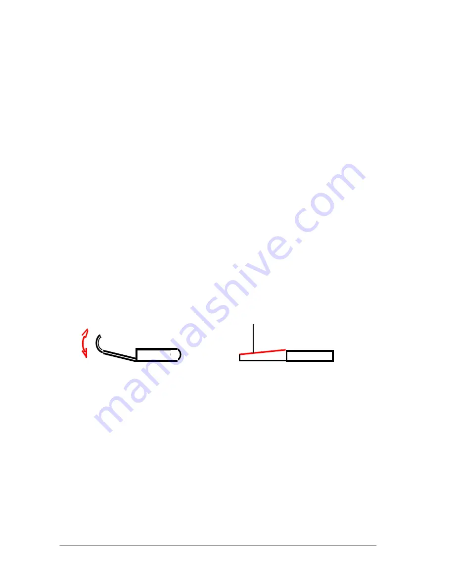
The final task is to adjust the capture arms by bending them to the point where they reliably engage in the
daughter boat. You may find it necessary to reduce the width of the capture arms slightly where they engage
in the daughter boat; this can be accomplished by careful use of a file.
NOTE:
repeated bending may cause
the sheet brass component to fracture, especially when bent through a tight radius, so please be very careful
when bending.
[
Adjust
this
edge
if
necessary
]
The function of the capture hook
The capture hook engages in the daughter boat immediately before the capture arms are lowered; the
hook’s own weight is sufficient to achieve this. Please ensure that the hook ‘overbalances’ at the end facing
the daughter boat; this simply means that this end has to be longer (approx. 2/3 of the overall hook length).
The hook must move with absolute freedom on its mountings; this includes the cable guide from the hook to
the hook servo. It is also very important that no cables etc. are left very close to the pull-cord, where they
could foul it, as this would prevent the operator having full control over the hook’s movement.
Attaching the capture bar to the daughter boat
At the daughter boat the bar on which the capture hook engages is fitted in such a way that it lies parallel to
the deck when the boat is in its cradle. The actual position should be selected to ensure that the hook is also
horizontal when it is engaged. The lift’s retaining pin (termed the ‘lift retaining bar’ in the instructions for No.
2027.100) should use a length of snake outer sleeve (3.2 / 2.1 mm Ø) inside the hull, with a suitable length
of snake inner sleeve (1.85 / 0.9 mm Ø) inside it acting as the actual retaining pin. This works very well as a
reliable method of capture, and its flexibility prevents it breaking off if the daughter boat should become
snagged at any point. Experience has shown that the alternative system described in the daughter boat
building instructions does not guarantee the same reliability of operation.
Construction of the rollers
The basic construction of the rollers is: snake inner sleeve as axle, ABS tube as the actual roller, and laser-
Diese Kante evtl. anpassen


