#
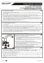
MONTAŻ ZAWORÓW I POKRĘTEŁ
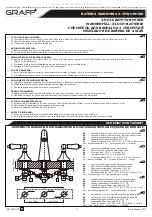
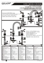
1) Sprawdź znacznik na zaworze (patrz „Schemat Montażowy” poz. A1 i B1) w celu identyfikacji zaworu
do ciepłej (czerwony znacznik) i zimnej (niebieski znacznik) wody.
2) Przełóż przez otwór montażowy wanny zawór
(14)
wraz z wcześniej nakręconą nakrętką
kołnierzową
(11)
i nałożoną podkładką gumową
(12)
.
3) Od góry nałóż na zawór podkładkę gumową i nakręć drugą nakrętkę kołnierzową, ale nie dokręcaj jej
zbyt mocno.
4) Od góry na zawór nałóż cokół pokrętła
(10)
i nakręć osłonę pokrętła
(9)
, a następnie nałóż dźwignię
(7b)
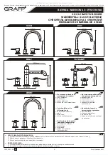
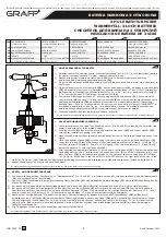
na wieloklin głowicy zaworu, sprawdź czy pozostawiony dystans „H” (rys.2) jest wystarczający
dla zapewnienia prawidłowego pasowania elementów 10, 9, 7b – jeśli nie – zdemontuj elementy 10,
9, 7b, skoryguj dystans „H” nakrętkami kołnierzowymi
(11)
.
5) Po wybraniu właściwego dystansu „H”, dokręć górną nakrętkę kołnierzową
(11)
. Ponownie nałóż
(*)
cokół pokrętła
(10)
na zawór i nakręć osłonę pokrętła
(9)
do momentu
odczucia wyraźnego oporu,
następnie nałóż dźwignię
(7b)
na wieloklin głowicy zaworu w odpowiedniej pozycji (obróć lewą
dźwignią (poz. 7b rys. 1a)
maksymalnie w lewą stronę, tak by zawór był w pozycji „ZAMKNIĘTY”, w
przypadku prawej dźwigni (poz. 7a, rys. 1a) maksymalnie w prawo).
Po wybraniu prawidłowego
położenia dokręć wkręt mocujący
(8)
kluczem imbusowym (załączony do baterii).
6) Powyższe czynności powtórz dla drugiego zaworu i pokrętła.
(*)
W celu lepszego przylegania powierzchni cokołu pokrętła do powierzchni wanny możesz nałożyć podkład silikonowy.
PL
#
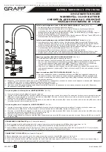
VALVE AND HANDWHEEL ASSEMBLY
1) Check the marker on the valve (see 'Assembly Layout' pts A1 and B1) to identify the hot water (red
marker) and cold water (blue marker) valves.
2) Feed the valve
(14)
along with the previously attached flange nut
(11)
and rubber washer
(12)
through the installation opening in the bath.
3) Place the rubber washer onto the valve from above and screw on the second flange nut, but not too
tightly.
4) Place the handwheel base
(10)
onto the valve from above and screw on the handwheel cover
(9)
,
then place the lever
(7b)
on the splines of the valve head, check that the distance 'H' left (fig. 2) is
sufficient to allow elements 10, 9 and 7b to fit properly if not, remove elements 10, 9 and 7b, and
adjust the distance 'H' with the flange nuts
(11)
.
5) After choosing the appropriate distance 'H', screw home the flange nut
(11)
. Replace the handwheel
(*)
base
(10)
onto the valve and screw on the handwheel cover
(9)
until clear resistance is felt, then
place the lever
(7b)
in the appropriate position on the splines of the valve head (turn the left lever
(pt. 7b, fig.1a) all the way to the left until it is in the OFF position, the right lever all the way to the
right (pt. 7a, fig.1a). After selecting the appropriate positioning screw home the attaching screw
(8)
with the spanner (included with the unit).
6) Repeat the above for the second valve and handwheel.
(*)
For better adhesion of the handwheel base's surface to the surface of the bath you may use silicon coating.
GB
2
G1/2"
G
1
/2
"
m
a
x
.
3
8
m
m
H
7b
8
9
10
14
12
11
#
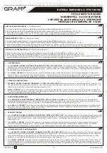
VENTIL- UND DREHGRIFFMONTAGE
1) Die Kennzeichnung auf dem Ventil prüfen (s. "Montageschema" Pos. A1 und B1), um Warmwasserventil (rote Kennzeichnung) und Kaltwasserventil
(blaue Kennzeichnung) zu identifizieren.
2) Das Ventil
(14)
zusammen mit der aufgeschraubten Überwurfmutter
(11)
und eingelegten Gummiunterlage
(12)
über die Montageöffnung des der
Wanne durchführen.
3) Auf das Ventil von oben eine Gummiunterlage einlegen und eine zweite Überwurfmutter aufschrauben, die Mutter nicht zu stark anziehen.
4) Auf das Ventil von oben ein Drehgriffsockel
(10)
aufstecken und die Griffhaube
(9)
aufschrauben, dann den Hebel
(7b)
auf die Keilwelle des
Ventilkopfes aufstecken und überprüfen, ob der gebliebene Abstand "H" (Abb. 2) ausreichend ist, um richtige Passung der Elemente 10, 9, 7b zu
sichern wenn nicht, die Elemente 10,9, 7b demontieren, den Abstand "H" mit den Überwurfmuttern
(11)
korrigieren.
(*)
5) Nachdem der richtige Abstand "H" gewählt ist, die obere Überwurfmutter
(11)
anziehen. Erneuet den Drehgriffsockel
(10)
auf das Ventil
aufstecken und die Griffhaube
(9)
bis zum spürbaren Widerstand anziehen, danach den Hebel
(7b)
auf die Keilwelle des Ventilkopfes in richtiger
Position aufstecken (linken Hebel (Pos.7b, Abb.1a) und maximal nach links drehen, so dass das Ventil in der Stellung "ZU" ist. Bei dem rechten
Hebel (Pos.7a, Abb.1a) maximal nach rechts drehen. Nach der Wahl der richtigen Lage die Befestigungsschraube
(8)
mit dem (beigelegten)
Inbusschlüssel anziehen.
6) O.g. Tätigkeiten für das zweite Ventil und den zweiten Griff wiederholen.
(*)
Um bessere Anlagefläche des Griffsockels an die Wannefläche zu erreichen, kann man Silikon benutzen.
D
5
IOG 2157.20
A
GB
PL
D
RUS
E
13b
14
15
16
17
18
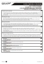
GŁOWICA LEWA
(otwierana w lewo)
KORPUS ZAWORU
PODKŁADKA GUMOWA
NAKRĘTKA KOŁNIERZOWA
TRÓJNIK
WĘŻYKI PRZYŁĄCZENIOWE
G1/2”GW-G3/4”GW, L=60cm
ЛЕВАЯ ГОЛОВКА
КОРПУС КЛАПАНА
РЕЗИНОВАЯ ПРОКЛАДКА
ФЛАНЦЕВАЯ ГАЙКА
ТРОЙНИК
ПОДСОЕДИНИТЕЛЬНЫЕ ШЛАН-
ГИ G1/2"GW-G3/4"GW, L=60cм
CARTUCHO IZQUIERDO
(abre hacia la izquierda)
CUERPO DE VÁLVULA
ARANDELA DE GOMA
TUERCA CON BRIDA
TUBO DE TRES VÍAS
MANGUERAS DE JUNTAR G1/2”GW-
G3/4”GW, L=60cm
KOPFSTÜCK LINKS
(gegen Urzeigersinn)
VENTILKÖRPER
GUMMIUNTERLAGE
FLANSCHMUTTER
T-STÜCK
ANSCHLUSSSCHLÄUCH
G1/2”GW-G3/4”GW, L=60cm
LEFT CARTRIDGE
(counterclockwise opening)
VALVE BODY
RUBBER WASHER
FLANGE NUT
T-PIPE
G1/2” i.t.-G3/4” i.t CONNECTOR
HOSES, L=60cm
Instrukcja Montażu i Obsługi
l
Instructions for assembly and use
l
Montage- und Gebrauchsanweisung
l
Инcтрукция по монтажу и обслуживанию
l
Instrucción de Montaje y Servicio
BATERIA WANNOWA 3-OTWOROWA
3-HOLE BATHTUB MIXER
WANNENFÜLL-3-LOCH-BATTERIE
СМЕСИТЕЛЬ ДЛЯ ВАННЫ НА 3 ОТВЕРСТИЙ
MEZCLADOR DE BAÑERA DE 3 VÍAS
Rev.2 October 2017
All manuals and user guides at all-guides.com


