


IT
E
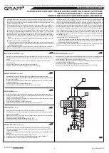
CONEXIÓN A LA INSTALACIÓN
1. Antes de conectar los grifos a la instalación de alimentación instale las mangueras de acometida (12)
según el “Esquema de Montaje”.
2. Al conectar los grifos a la instalación de alimentación preste atención en la conexión adecuada del agua
caliente y fría: a la válvula a la izquierda conecte la alimentación del agua caliente, a la válvula a la
derecha conecte la alimentación del agua fría.
3. El grifo está equipado en mangueras de alimentación con tubos de acometida G1/2” RI - G3/8” RI de
450mm de longitud. Si ya tiene montados grifos angulares con filtro (en la alimentación del agua
caliente y fría), terminados con el tubo de acometida G1/2" RZ, use las mangueras con tubos de
acometida G1/2” RI - G1/2” RI de longitud adaptada a sus necesidades (disponibles por separado).
COLLEGAMENTO ALL'IMPIANTO
1. Prima di procedere al collegamento della batteria all'impianto di alimentazione, monta i flessibili di
collegamento (12) conformemente allo „Schema di Montaggio”.
2. Collegando la batteria all'impianto di alimentazione, fai attenzione al corretto collegamento
dell'alimentazione dell'acqua calda e fredda: alla valvola sulla sinistra collega l'alimentazione con acqua
calda, alla valvola sulla destra collega l'alimentazione con l'acqua fredda.
3. La batteria è dotata di flessibili di alimentazione con attacchi G1/2” FI - G3/8” FI della lunghezza di 450
mm. Se possiedi dei rubinetti angolari con il filtro, già montati (sull'alimentazione dell'acqua calda e
fredda), che terminano con attacchi G1/2” FE, usa i flessibili con attacchi G1/2” FI - G1/2” FI dalla
lunghezza adeguata ai bisogni individuali (accessibili separatamente).
CONNECTING TO THE SUPPLY SYSTEM
1. Before attempting to connect the mixer to the supply system, install the connecting hoses (12) according
to the “Assembly Diagram”.
2. When connecting the mixer to the supply system, take care to connect the hot and cold water supply
system correctly: connect the hot water supply system to the left valve and the cold water system to the
right valve.
3. The mixer is fitted with 450mm long feeding hoses with G1/2" FT - G3/8" FT connectors. If you have
angle valves with filters (on hot and cold water supply) fitted with G1/2" MT connector, use the hoses of
appropriate length with G1/2" FT - G1/2" FT connectors (not included).
ANSCHLUSS AN DIE ANLAGE
1. Vor dem Wasserinstallationsanschluss der Mischbatterie müssen die Anschlussschläuche (12) gemäß
der „Montagedarstellung“ montiert werden.
2. Beim Anschluss der Mischbatterie an die Wasserinstallation ist auf richtigen Warm- und
Kaltwasseranschluss zu achten: die Warmwassereinspeisung muss an das linke und die
Kaltwassereinspeisung an das rechte Ventil angeschlossen werden.
3. Die Batterie ist mit den Einspeiseschläuchen mit Anschlüssen G1/2” IG - G3/8” IG mit einer Länge von
450mm ausgestattet. Falls bei Ihnen die Eckhähne mit dem Filter und mit dem G1/2" AG-Anschluss
installiert sind, müssen Schläuche mit G1/2” IG - G1/2” IG-Anschlüssen mit einer entsprechenden
bedarfsgerechten Länge (separate Bestellung) einzusetzen.
GB
D
ПОДКЛЮЧЕНИЕ К СИСТЕМЕ
1. Перед приступлением к подключению смесителя к системе подачи воды установи
присоединительные шланги (12) согласно „Монтажной схеме”.
2. При подключении смесителя к системе подачи воды к системе питания обрати внимание на
правильное подключение подвода горячей и холодной воды: к клапану с левой стороны
подключи подачу горячей воды, а к клапану с правой стороны - подачу холодной воды.
3. Смеситель оснащен шлангами подачи воды с патрубками G1/2” GW - G3/8” GW длиной 450мм.
Если у Тебя установлены угловые краны с фильтром (на подаче горячей и холодной воды),
законченные патрубком G1/2” GZ, используй шланги с патрубками G1/2” GW - G1/2” GW длиной,
подобранной по индивидуальным потребностям (доступны отдельно).
RACCORDEMENT A L'INSTALLATION
1. Avant de procéder au raccordement de la robinetterie à une installation extérieure, fixez les flexibles de
raccordement (12) conformément au «Schéma de montage».
2. Lors du raccordement de la robinetterie à l'installation d'alimentation veillez à ce que l'alimentation en
l'eau chaude et l'eau froide soit effectuée correctement : raccordez l'alimentation en eau chaude à la
vanne située à gauche et l'alimentation en eau froide à la vanne située à droite.
3. La robinetterie est équipée de flexibles avec raccords G1/2” FI - G3/8” FI d'une longueur de 450mm. Si
vous avez installé des vannes d'angle avec filtre (sur les alimentations en eau chaude et froide)
équipées d'un raccord G1/2” FE, utilisez des flexibles avec raccords G1/2” FI - G1/2” FI de longueurs
adaptées aux besoins individuels (disponibles séparément).
F
RUS
7
GB D
F RUS E
IT
WASCHBECKENMISCHBATTERIE MIT 3 ÖFFNUNGEN, STEHEND • ROBINETTERIE DE LAVABO 3 TROUS À POSER
СМЕСИТЕЛЬ ДЛЯ УМЫВАЛЬНИКА С 3 ОТВЕРСТИЯМИ СТОЯЩИЙ
GRIFOS DE LAVABO DE 3 HUECOS • BATTERIA PER LAVABO A 3-FORI VERTICALE
Instructions for assembly and use • Montage- und Gebrauchsanweisung • Notice technique montage et utilisation • Инcтрукция по монтажу и обслуживанию • Instrucción de Montaje y Servicio • Manuale di Montaggio e Uso
THREE-HOLE STANDING BASIN MIXER
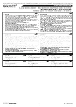
AUTOMATIC DRAIN ASSEMBLY INSTALLATION • AUTOMATIK-ABLAUFSATZ MONTIEREN • MONTAGE DU MÉCANISME D'ÉVACUATION D'EAU AUTOMATIQUE
MOНТАЖ АВТОМАТИЧЕСКОГО СЛИВНОГО КОМПЛЕКТА • INSTALACIÓN DEL JUEGO DE DESAGÜE AUTOMATICO • MONTAGGIO DEL GRUPPO DI SCARICO AUTOMATICO
GB
D
F
RUS
E
IT
1
2
3
4
5
6
7
Drain body
Drain collar
Drain plug
Drain switch assembly
Under-bowl gasket
Collar gasket
Washer
Ablaufsatzkörper
Ablaufsatzflansch
Ablaufverschluss
Ablaufumschalter-Baugruppe
Untere Dichtung
Flanschdichtung
Unterlegscheibe
Corps du mécanisme d'évacuation
Bride du mécanisme d'évacuation
Bouchon du mécanisme
d'évacuation
Module du commutateur du
mécanisme d'évacuation
Joint inférieur
Joint à bride
Rondelle
Корпус слива
Фланец слива
Сливная пробка
Блок переключателя слива
Нижнее уплотнение
Фланцевая прокладка
Шайба
Cuerpo de desagüe
Anillo de desagüe
Tapa protectora
Juego de alternador de desagüe
Junta inferior
Junta superior del anillo
Arandela
Corpo dello scarico
Flangia dello scarico
Tappo dello scarico
Gruppo del deviatore dello scarico
Guarnizione inferiore
Guarnizione a collare
Rondella
S
ee fig.
4
1. Remove drain body (1) with under-bowl gasket (5) from drain collar (2).
2. Insert drain collar (2) with collar gasket (6), drain plug (3) and drain switch assembly (4) into drain hole
of a bidet.
3. From underneath the bidet thread drain body (1) with under-bowl gasket (5) onto drain collar (2).
Hand tighten only.
4. Screw the discharge pipe of the sewer trap (not available in the drain assembly set) to the threaded
G 1-1/4” stub pipe of the drain body (1).
GB
Siehe Abb.
4
1. Ablaufsatzkörper (1) mit unterer Dichtung (5) vom Ablaufsatzflansch (2) abschrauben.
2. Ablaufsatzflansch (2) mit der Flanschdichtung (6), Ablaufverschluss (3) und Ablaufumschalter-
Baugruppe (4) in die Ablauföffnung im Bidet einsetzen.
3. Ablaufsatzkörper (1) mit unterer Dichtung (5) auf Ablaufsatzflansch (2) mit der Hand schrauben.
4. Handelsübliches Sifonablaufrohr (im Bausatz nicht enthalten) am Gewinde G 1-1/4” des
Ablaufsatzkörpers (1) schrauben.
D
Voir schéma 4
1. Dévissez le corps du mécanisme d'évacuation (1) et enlevez le joint inférieur (5) de la bride du
mécanisme d'évacuation (2).
2. Placez la bride du mécanisme d'évacuation (2), le joint à bride (6), le bouchon du mécanisme d'évacuation
(3) et le module du commutateur du mécanisme d'évacuation (4) dans l'orifice d'évacuation du bidet.
3. Par en-dessous, vissez le corps du mécanisme d'évacuation (1) et le joint inférieur (5) sur la bride du
mécanisme d'évacuation (2). Effectuez le serrage à la main.
4. Vissez sur la tubulure filetée G 1-1/4” du corps du mécanisme d'évacuation (1) le tuyau d'évacuation de
la bonde (a acheter séparément).
F
См. рис. 4
1. Отвинтите от фланца слива (2) корпус слива (1) с нижним уплотнением (5).
2. Вставьте фланец слива (2) с фланцевой прокладкой (6), сливную пробку (3) и блок передключателя
слива (4) в сливное отверстие биде.
3. Снизу биде привинтите корпус слива (1) с нижним урлотнением (5) на фланец слива (2) и затяните
вручную.
4. К патрубку с резьбой
на корпусе слива (1) привинтите отводящую трубу сифона (сифон
приобретается дополнительно).
G 1-1/4”
RUS
Vea dis. 4
1. Quitar el cuerpo de desagüe (1) con la junta inferior (5) del anillo de desagüe (2).
Colocar el anillo de desagüe (2) con la junta del anillo (6), tapa protectora (3) y el juego de alternador de
desagüe (4) en el agujero de desagüe del bidé.
Por la parte de abajo de bidé colocar el cuerpo de desagüe (1) con la junta inferior (5) en el anillo de
desagüe (2). Apretar únicamente a mano.
Enrosque al racor con rosca G 1-1/4” del cuerpo de la desagüe (1) un tubo de descarga del sifón (no
forma parte del producto).
2.
3.
4.
Vedi fig. 4
1. Svita il corpo dello scarico (1) con la guarnizione inferiore (5) dalla flangia dello scarico (2).
Metti la flangia dello scarico (2) con la guarnizione a collare (6), il tappo dello scarico (3) e il gruppo del
deviatore dello scarico (4) nel foro dello scarico nel bidet
Dal basso del bidet avvita il corpo dello scarico (1) con la guarnizione inferiore (5) sulla flangia dello
scarico (2). Serra a mano.
Al tubo di giunzione con il filetto G 1-1/4” del corpo dello scarico (1) avvita il tubo di scarico del sifone
(reperibile per conto proprio).
2.
3.
4.
E
IT
IOG 5120.50
Rev. 2 March 2015