


4
GB D
F RUS E
IT
WASCHBECKENMISCHBATTERIE MIT 3 ÖFFNUNGEN, STEHEND • ROBINETTERIE DE LAVABO 3 TROUS À POSER
СМЕСИТЕЛЬ ДЛЯ УМЫВАЛЬНИКА С 3 ОТВЕРСТИЯМИ СТОЯЩИЙ
GRIFOS DE LAVABO DE 3 HUECOS • BATTERIA PER LAVABO A 3-FORI VERTICALE
Instructions for assembly and use • Montage- und Gebrauchsanweisung • Notice technique montage et utilisation • Инcтрукция по монтажу и обслуживанию • Instrucción de Montaje y Servicio • Manuale di Montaggio e Uso
THREE-HOLE STANDING BASIN MIXER
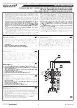
MONTAGE DES CLAPETS ET DU LEVIER - voir schéma 2.1-2.10
1. Vérifier le marqueur de la vanne afin d'identifier la vanne d'eau chaude (étiquette rouge) et d'eau froide
(étiquette bleu). Monter la vanne d'eau chaude à droite du robinet et la vanne d'eau froide à gauche.
2. Vissez l'écrou (16) sur la vanne (13L) et placez la rondelle métallique (17) et la rondelle caoutchouc (18)
- schéma 2.1. Insérez la vanne dans le perçage de fixation par le dessous du lavabo (13L). Maintenez la
vanne (13L) et approchez la bride de vanne en la vissant par le haut (19) jusqu'au contact - schéma 2.2.
Après avoir positionné la vanne correctement par le dessous du lavabo, serrez l'écrou (16).
3. Placez le support du sélecteur rotatif (20) et la rondelle de friction (22) sur la surface de montage. Placez
correctement le support par rapport à la bride de vanne (19) et bloquez-le grâce à la vis de fixation (21)
à l'aide de la clé Allen jointe (K1) - schéma 2.3-2.4.
4. Afin de vous assurer que la vanne est en position « vanne fermée », tournez la tige de vanne à droite (la
vanne d'eau chaude (13L) porte une étiquette rouge) jusqu'au moment où vous sentez une résistance.
Dans le cas de la vanne d'eau froide (13R) portant une étiquette bleu, tournez la tige de vanne à gauche.
5.
МОНТАЖ КЛАПАНОВ И РУКОЯТОК - cм. рис. 2.1-2.10
1. Проверь маркер на клапане для идентификации клапана для горячей воды (красная этикетка)
и для холодной воды (синяя этикетка). Клапан для горячей воды установи с левой стороны
излива, а клапан для холодной воды - с правой стороны.
2. Навинти гайку (16) на клапан (13L) и надвинь металлическую прокладку (17) и резиновую (18) -
рис. 2.1. Снизу умывальника в монтажное отверстие вложи клапан (13L). Придерживая клапан
(13L) навинти сверху фланец клапана (19) до упора - рис. 2.2. После установления клапана
в соответствующее положение снизу умывальника затяни гайку (16).
3. На монтажной поверхности установи гильзу воротка (20) вместе со скользящей подкладкой (22).
Установи гильзу в соответствующем положении по отношению к фланцу клапана (19)
и зафиксируй установочным винтом (21) при помощи приложенного имбусного ключика (K1) -
рис. 2.3-2.4.
4. Убедись, что клапан находится в положении „клапан закрыт”, для этого надо повернуть
шпиндель клапана вправо (клапан для горячей воды (13L), обозначенный красной этикеткой),
пока не почувствуешь ощутимое сопротивление. В случае клапана для холодной воды (13R),
обозначенного синей этикеткой - поверни шпиндель клапана влево.
5.
F
RUS
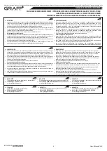
– Si le positionnement du levier (A) est toujours incorrect, décalez la tige de commande de tête (14)
d'une dent supplémentaire sur la tête crantée et assurez-vous de nouveau que le positionnement de
levier est correct (A).
6. Apres avoir fixé la vanne d'eau chaude (13L) et le levier (A) procédez au montage de la vanne d'eau
froide (13R) en respectant l'ordre de montage indiqué ci-dessus.
– Если и теперь положение рычага (A) неудовлетворительное - переставь удлинение веретена
клапана (14) еще на один зубец на поликлине головки клапана и опять проверь, правильно ли
установлен рычаг (A).
6. После установки клапана для горячей воды (13L) и рычага (A) приступи к монтажу клапана для
холодной воды (13R), соблюдая вышеописанную очередность действий по установке.
Placez le corps du levier (23) avec la vis (24) sur la tige de commande de tête (14) - schéma 2.5.
Assurez-vous que le positionnement du levier est conforme au schéma 2.9. Si vous n'êtes pas en
mesure d'obtenir un positionnement satisfaisant du levier (A) par rapport au bord du lavabo (vous
notez un décalage remarquable d'un angle Δ par rapport au positionnement exigé - tel que représenté
dans le schéma 2.6) enlevez le levier (A) de la tige de commande de tête (14) - schéma 2.7.
Desserrez la vis (15) et déplacez la tige de commande de tête (14) d'une dent sur la tête crantée de
la vanne et resserrez la vis (15) - schéma 2.8. Remettez le levier (A) sur la tige de commande de tête
(14) et assurez-vous que le positionnement du levier est correct (A) - schéma 2.9.
– Si le positionnement du levier (A) est correct, serrez la vis (24) à l'aide de la clé Allen (K1)
conformément au schéma 2.10.
На удлинение веретена клапана (14) надвинь корпус рычага (23) с болтом (24) - рис. 2.5.
Проверь, можно ли достичь положения рычага, как на рис. 2.9. Если Ты не можешь достичь
нужного положения рычага (A) по отношению к краю умывальника (заметишь явное смещение
на угол Δ от требуемого положения, показанного на рис. 2.6) сними рычаг (A) с удлинения
веретена клапана (14) - рис. 2.7. Отвинти винт (15) и переставь удлинение веретена клапана
(14) на один зубец на поликлине головки клапана и опять завинти винт (15) - рис. 2.8 . Опять
установи рычаг (A) на удлинение веретена клапана (14) и проверь, правильно ли установлен
рычаг (A) - рис. 2.9.
– Если положение рычага (A) правильное, отвинти плечо рычага (25) и затяни болт (24)
имбусным ключиком (K1), как показано на рис. 2.10.
IT
E
MONTAJE DE VÁLVULAS Y PALANCAS - ver. fig. 2.1-2.10
1. Comprobar el troquel en la válvula para identificar la válvula para el agua caliente (etiqueta roja) y para
el agua fría (etiqueta azul). Montar la válvula para el agua caliente al lado izquierdo del caño, la válvula
para el agua fría - al lado derecho.
2. Atornillar la tuerca (16) en la válvula (13L) y poner la junta de metal (17) y de caucho (18) - fig. 2.1. Por
debajo del lavabo, en el orificio de montaje introducir la válvula (13L). Sosteniendo la válvula (13L)
atornillar por encima la brida de la válvula (19) hasta sentir resistencia - fig. 2.2. Fijada la válvula en la
posición adecuada, por debajo del lavabo, atornillar la tuerca (16).
3. En la superficie de montaje situar la base de la perilla (20) junto con la arandela deslizante (22). Situar la
base en la posición adecuada en relación a la brida de la válvula (19) y proteger con el tornillo fijador
(21) usando para ello la llave Allen que va incluido (K1) - rys.2.3-2.4.
MONTAGGIO DELLE VALVOLE E DELLA LEVA - vedi fig. 2.1-2.10
1. Verifica l'indicatore sulla valvola allo scopo di identificare la valvola dell'acqua calda (etichetta rossa) e
dell'acqua fredda (etichetta blu). Monta la valvola dell'acqua calda dalla parte sinistra della bocca, la
valvola dell'acqua fredda - dalla parte destra.
2. Avvita il dado (16) sulla valvola (13L) e metti la guarnizione di metallo (17) e di gomma (18) - fig. 2.1. Dal
basso del lavabo metti nel foro di montaggio la valvola (13L). Tenendo la valvola (13L) avvita dall'alto il
collare della valvola (19) fino alla resistenza - fig. 2.2. Dopo la disposizione della valvola in posizione
corretta dal basso dell'lavabo serra il dado (16).
3. Sulla posizione di montaggio disponi lo zoccolo della manopola (20) insieme alla rondella di usura (22).
Disponi lo zoccolo in posizione corretta rispetto al collare della valvola (19) e fissa con la vite di fissaggio
(21) usando la chiave a brugola in dotazione (K1) - fig.2.3-2.4.
IOG 5120.50
Placez les capots
(29)
.
.
Вставить заглушки
(29)
.
INSTALLATION OF VALVES AND LEVERS - see figs. 2.1-2.10
1. Check the label on the valve in order to identify hot water valve (red label) and cold water valve (blue
label). Install the hot water valve on the left side of the spout, and the cold water valve on its right side.
2
.
Screw the nut (16) on the valve (13L) and put metal gasket (17) and rubber gasket (18) - figure 2.1. Insert
the valve (13L) through the installation opening from under the sink. From above, screw the valve flange
(19) home, at the same time holding the valve (13L) - figure 2.2. After proper positioning of the valve
under the sink, screw the nut (16).
3
.
Put the knob unit base (20) on the base together with the sliding washer (22). Put the unit base in the
correct position against the valve flange (19) and secure it with a set screw (21) using the hex key
supplied (K1) - figure 2.3-2.4.
4
.
Make sure the valve is in “closed” position by turning the valve spindle to the right (hot water valve (13L)
marked with red label) until you feel strong resistance. For the cold water valve (13R), marked with blue
label, turn the valve spindle to the left.
5
.
– However, if the position of the lever (A) is still incorrect, move the valve spindle extension (14) one
more tooth on valve head splines and check the lever (A) positioning once again.
6. After installation of the hot water valve (13L) and the lever (A), repeat the above mentioned steps for
installing the cold water valve (13R).
VENTIL- UND HANDHEBELMONTAGE - siehe Abb. 2.1-2.10
1. Die Markierung am Ventil prüfen um das Warmwasserventil (rote Markierung) und das Kaltwasserventil
(blaue Markierung) identifizieren zu können. Warmwasserventil links und Kaltwasserventil rechts an
der Auslaufgarnitur einbauen.
2. Die Mutter (16) auf das Ventil (13L) aufschrauben und eine Metallscheibe (17) sowie eine
Gummischeibe (18) aufsetzen - Abb. 2.1. In die Montageöffnung von der Unterseite des Waschbeckens
her das Ventil (13L) einlegen. Halten Sie das Ventil (13L) und von oben drehen Sie den Ventilflansch
(19) bis zum Anschlag auf - Abb. 2.2. Nach der Positionierung des Ventils in einer richtigen Lage von der
Waschbeckenunterseite her ist die Mutter (16) anzuziehen.
3. Auf die Montagefläche den Drehradsockel (20) samt der Gleitscheibe (22) einstellen. Den Sockel richtig
gegenüber den Ventilflansch (19) positionieren und mit der Feststellschraube (21) mit Hilfe des
beiliegenden Innensechskantschlüssels (K1) sichern - Abb.2.3-2.4.
4. Sicherzustellen, dass sich das Ventil in der Stellung „Ventil geschlossen“ befindet, dazu ist die
Ventilspindel bis zum spürbaren Widerstand nach rechts (Warmwasserventil (13L) mit roter
Markierung) bis zum spürbaren Widerstand zu drehen. Beim Kaltwasserventil (13R) mit blauer
Markierung ist die Ventilspindel nach links zu drehen.
5.
– Falls die Stellung des Hebels (A) weiterhin falsch bleibt - ist die Ventilspindelverlängerung (14) um den
nächsten Zahn der Keilwelle des Ventils zu verstellen und Positionierung des Hebels (A) zu prüfen.
6. Nach der Montage des Warmwasserventils (13L) und des Hebels (A) ist die Montage des
Kaltwasserventils (13R) in oben genannter Reihenfolge durchzuführen.
GB
D
Place the lever body (23) with the bolt (24) on the valve spindle extension (14) - fig. 2.5. Check, if you
are able to obtain the required lever position, according to fig. 2.9. If you cannot position the lever (A)
correctly in relation to the sink edge (you notice distinct shift of Δ angle to the required positioning - as
shown on fig. 2.6) Take the lever (A) off the valve spindle extension (14) - see fig. 2.7. Loose the tap
bolt (15) and move the valve spindle extension (14) one tooth on valve head splines and screw the tap
bolt (15) back into position - fig. 2.8. Place the lever (A) on the valve spindle extension (14) and check
the correct positioning of the lever (A) - fig. 2.9.
– If the position of the lever (A) is proper, tighten the screw (24) using hex key (K1) according to the
drawing 2.10.
Auf die Ventilspindelverlängerung (14) den Hebelkörper (23) mit der Schraube (24) aufsetzen - Abb.
2.5. Es ist zu prüfen, ob die Hebelstellung nach Abb. 2.9 erreicht werden kann. Falls keine zufrieden
stellende Hebelstellung (A) gegenüber der Waschbeckenkante erreicht werden kann (es wird eine
Verstellung um Δ-Winkel von der geforderten Stellung sichtbar - wie in der Abb. 2.6), so ist der Hebel
(A) von der Ventilspindelverlängerung (14) abzunehmen - Abb. 2.7. Die Schraube (15) losziehen und
die Ventilspindelverlängerung (14) um einen Zahn an der Keilwelle (15) des Ventils verstellen, danach
das Ventil erneut eindrehen - Abb. 2.8. Den Hebel (A) erneut auf die Ventilspindelverlängerung (14)
aufsetzen und die Richtigkeit der Hebelpositionierung (A) prüfen - Abb. 2.9.
– Falls die Positionierung des Hebels (A) richtig ist, die Schraube (24) mit dem
(K1)
.
Push the hole plugs
(29)
in.
(29)
Innensechskantschlüssel
nach Abb. 2.10 anziehen
Die Blindplatten
aufschieben.
Rev. 2 March 2015


