


Instruction Manual GRAF SINGLE LUB 2 / Version 4.0
–
05.2020
22
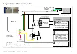
7. Diagram electrical installation on winding machines
If present, connect the
other Single Lub 2 the
same way as it is
shown for this device.
A1 (+)
A2 (-)
12
11
14
green
brown
white
yellow
grey
white
yellow
grey
Relay R1
(Running/Stopping
the Single Lub 2)
0VDC
Relay R2
24VDC
(SPCO)
graf
Single Lub 2
+24VDC
0VDC
green
brown
+24VDC
Power Supply
24VDC / 1,2A per device
IMPORTANT:
For enabling the Single Lub 2, on some machines
the “Graf oiling
System”
, has to be enabled in the Machines P.L.C. settings.
For details, please refer to the Machines manual.
230V~ (L)
0V~ (N)
(PE)
L
N
PE
V-
V+
Separate Power Supply
AC Mains
Power Supply
from Machine
Winding machine electronic
control unit
(one single spindle only)
A1
A2
Interface Output for running/stopping
the Single Lub 2.
Energizing the Relay R1 will start the
device. (Relay contact 11-14 closes)
De-energizing the Relay R1 will stop the
device. (Relay contact 11-14 opens)
User proper Relais operating voltage and
current type (DC/AC) to meet the
interface output capabilities.
OK
fault
Interface Input for stopping the
spindle in case of fault detected by
the Single Lub 2.
In case of normal operation of the Single
Lub 2, Relay R2 is energized and contact
between I1 and I2 is closed (Relay
contact 11-14 closes)
In case of a fault has been detected,
Relay R2 is de-energized and contact
between I1 and I2 is open (Relay contact
11-14 opens)
I1
I2
A3
Interface Output for Lube speed
control (Optionally)
In case of non-constant winding speed,
this speed clock signal (0V-24V p-p) can
control the Lube rate if necessary
(optionally)
A1 (+)
A2 (-)
12
11
14
*
run
stop
*
Connect Protection Diode only for
DC-driven Relays in order to protect
the machine interface output stage.
Protective earthing
pink


