


the designation
“3”
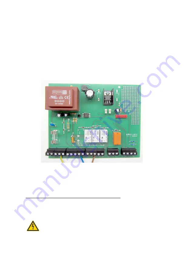
(power supply to the filter flushing valve). The following figure
depicts the connections described above:
1: Pump
2: Power supply to additional pump
3: Power supply to filter flushing valve
4: Power supply to switch-over valve
5: Neutral conductor
P: 230V AC
PE / Ground : Earth
Figure 4: Electrical diagram for filter flushing valve
After connecting the wires, close the lower cover
[7]
of the system control housing.
4.4 Electrical connection of the additional pump:
Connection of the additional pump is optional. If running the system without the
additional pump please read from point 3 (putting into operation).
Before opening the equipment pull the plug out from the mains socket!
Page 12
Содержание SILENTIO
Страница 27: ...Room for your notes Page 27 ...