


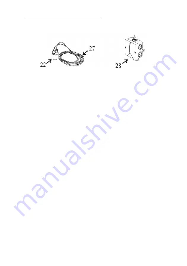
4 .2 Connection sensors and data cable:
The sensor electronics comprise of a stainless steel probe
[22]
with a red and a
white connecting cable
[27]
and the sensor measurement pick-up
[28]
.
Figure 3: Sensor technology
1. Now the sensor measurement pick-up
[28]
(cover removed) should be
installed on the tank wall (preferably in the man hole shaft of the Graf
synthetic tank). The location of the mounted sensor pick-up should be
between 10 and 15 cm above the overflow
[25]
. The enclosed screws
should be used to secure the device. After fully tightening the screws, the
points that are showing themselves on the outside of the tank must be
blunted to avoid injury
[24]
.
2. Measure the height from the bottom of the tank
[23]
to the end of the
terminals
[15]
and
[16]
on the measurement pick-up
[28]
.
3. Shorten the connection cable to suit the measured height.
4. Connect the sensor cable to the sensor as described in the following
instructions: Remove between 5-7 mm of the insulation from both of the
cables. Next, pass the red cable through the screw mounting 1
[19]
and
tighten this lightly, then connect the red cable to the terminal
[16
]. The
free white cable is now passed through the screw mounting 2
[18]
and
tightened lightly, then connect the white cable to the terminal
[15]
.
5. Now pass the end of the data cable that has no plug connector
[12]
through the screw mounting 3
[13]
. Lightly tighten the screw mounting
and connect the cable wire cores of the data cable
[12]
to the double
terminal
[14]
.
The connection of the data cable is reverse polarity
protected.
Attention! The screws should be tightened with care to
ensure that they are not damaged through over tightening.
6. Now recheck that all the screwed items and the sensor components have
Page 10
Содержание SILENTIO
Страница 27: ...Room for your notes Page 27 ...