


•
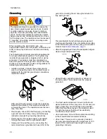
Floor of the spray area:
The floor must be
electrically conductive and grounded. Do not cover
the floor with cardboard or any non-conductive
material which would interrupt grounding continuity.
•
All solvent pails:
Use only grounded metal
containers, which are conductive. Do not use
plastic containers. Use only non-flammable
solvents. Do not store more than the quantity
needed for one shift.
• All persons entering the spray area must wear
shoes having conductive soles such as leather,
or wear personal grounding straps. Do not
wear shoes with non-conductive soles such as
rubber or plastic. If gloves are necessary, wear
the conductive gloves supplied with the gun. If
non-Graco gloves are worn, cut off fingers or palm
area of gloves to ensure your hand contacts the
grounded gun handle. Conductive gloves and
footwear must not exceed 100 megohm per EN
ISO 20344, EN 1149–5.
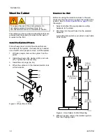
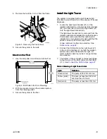
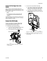
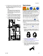
Connect
Connect
Connect the
the
the Hoses
Hoses
Hoses
To reduce the risk of electric shock, install only
one continuous Graco waterborne hose between
the isolation cabinet and the gun. Do not splice
hoses together.
Always use a Graco waterborne fluid hose between
the fluid outlet on the isolation cabinet and the gun
fluid inlet.
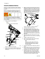
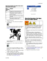
When setting up the isolation system for the first time,
connect the hoses in the following order:
1.
Fluid hose from the gun to
the isolation cabinet.
See
Connect the Waterborne Fluid Hose, page 18
.
2.
Air hose from the gun to the isolation cabinet.
See
Connect the Air Hose from Gun to the
.
3.
Air hose from the air supply to the isolation
cabinet. See
Connect the Air Supply Hose to the
.
4.
Fluid hose from the fluid supply to the isolation
cabinet. See
Connect the Fluid Supply Hose to
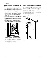
Note
• If the air hose or the fluid hose must pass
through the wall of a booth to the isolation
cabinet, make sure that the hole through
the booth wall does not have sharp edges
that could damage the hoses.
• The holes in the wall must be large enough
to allow the hose fittings to pass through.
3A7370B
17
Содержание HydroShield WMBH00
Страница 76: ...Repair Figure 42 Electrical Schematic for 26C716 Electrical Control equipped for gun flush box 76 3A7370B ...
Страница 82: ...Parts Figure 46 Isolation Cabinet Interior 82 3A7370B ...
Страница 88: ...Parts 25N031 25N031 25N031 Pump Pump Pump Parts Parts Parts Figure 48 Pump 88 3A7370B ...


