


2.
Attach the isolation valve to the bottom of the
cabinet stand (9):
a.
Insert the two screws (54) through the base
housing (201) and then into the bottom two
holes of the cabinet stand (9).
b.
The front screw also holds the bottom
bracket for the isolation valve cover (98).
Thread the front bracket (16) onto the front
screw, followed by the washer (19), lock
washer (22), and hex nut (23). Tighten with
a wrench.
c.
Thread the washer (19), lock washer (22),
and hex nut (23) onto the back screw.
Tighten with a wrench
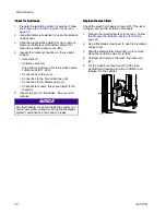
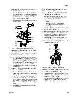
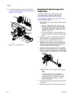
3.
Attach the inlet fluid tube, using one wrench to
orient the elbow fitting (72) and one wrench to
tighten it to the housing (218).
4.
Place the two clamps (101) over the top of the air
cylinder (227) and attach the top sensor to the
top clamp and the bottom sensor to the bottom
clamp.
5.
If the sensor positions were indicated
during disassembly, attach the clamps into
position. If the position was not indicated, see
Adjust the Isolation Valve Sensor, page 62
6.
Fill the wash fluid reservoir (69) with wash fluid
and return to the cabinet. Connect to the back
port (91).
Adjust
Adjust
Adjust the
the
the Isolation
Isolation
Isolation Valve
Valve
Valve Sensor
Sensor
Sensor
When disassembling the isolation valve, you may
have indicated the positions of the top and bottom
valve sensors. If the positions were not indicated,
use this procedure to determine the positions of the
sensors.
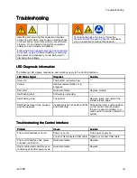
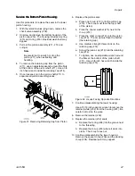
1.
Determine the location of the top sensor:
a.
On the control interface, enter Off mode.
Navigate to the Status menu.
b.
Raise the isolation valve to the top position.
c.
Position the sensor and watch the Status
menu. When the Shuttle Top circle changes
from gray to yellow, attach the clamp in that
position.
2.
Determine the location of the bottom sensor:
a.
On the control interface, enter Standby
mode. Standby mode drives the isolation
valve to the bottom position.
b.
Position the sensor and watch the Status
menu. When the Shuttle Bottom circle
changes from gray to yellow, attach the
clamp in that position.
Figure 23 Isolation Valve Sensor Position
on Status Menu
Disassemble
Disassemble
Disassemble the
the
the Isolation
Isolation
Isolation Valve
Valve
Valve
Components
Components
Components
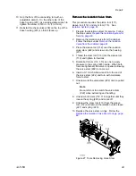
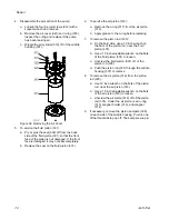
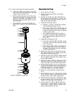
Use this procedure to disassemble the air cylinder
(227), block mount (224), connecting rods (225),
shuttle housing (218), and base housing (201).
1.
Prepare the isolation system for service. Follow
the steps under
Prepare the Isolation System for
2.
Remove the isolation valve from the cabinet.
Follow the steps under
Valve from the Cabinet, page 61
.
62
3A7370B
Содержание HydroShield WMBH00
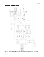
Страница 76: ...Repair Figure 42 Electrical Schematic for 26C716 Electrical Control equipped for gun flush box 76 3A7370B ...
Страница 82: ...Parts Figure 46 Isolation Cabinet Interior 82 3A7370B ...
Страница 88: ...Parts 25N031 25N031 25N031 Pump Pump Pump Parts Parts Parts Figure 48 Pump 88 3A7370B ...


