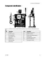


Connect
Connect
Connect the
the
the Fluid
Fluid
Fluid Supply
Supply
Supply Hose
Hose
Hose to
to
to the
the
the
Cabinet
Cabinet
Cabinet
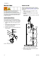
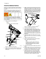
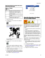
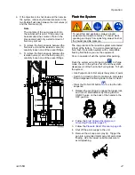
Use a wrench to connect the fluid supply hose
between the fluid supply and the fluid inlet (F) on the
isolation cabinet. The maximum fluid pressure is 100
psi (0.7 MPa, 7.0 bar).
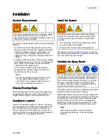
Note
For the system to function correctly, the inlet
fluid pressure must not exceed the inlet air
pressure.
Consider installing a manual fluid shut-off valve (FV)
close to the cabinet to easily turn off the fluid supply
during installation or service.
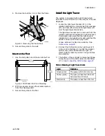
Connect
Connect
Connect the
the
the CAN
CAN
CAN Cables
Cables
Cables
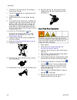
Connect the Control Area Network (CAN) cables
to the control interface so that the interface can
communicate with the isolation system.
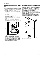
1.
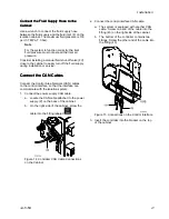
Connect the power supply CAN cable:
a.
Locate the CAN cable attached to the power
supply (P) on the back of the cabinet.
b.
On the right side of the cabinet, screw the
cable into the fitting labeled
.
Figure 14 Controller CAN Cable Connections
on the Cabinet
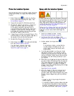
2.
Connect the control interface CAN cable:
a.
The system is equipped with another CAN
cable. Screw one end of the cable into the
fitting (43) on the right side of the cabinet.
b.
The bottom of the controller contains two
fittings. Screw the other end of the cable into
the fitting (43).
Figure 15 Connections on the Control Interface
3.
Insert the controller into the bracket on the top
of the cabinet.
3A7370B
21
Содержание HydroShield WMBH00
Страница 76: ...Repair Figure 42 Electrical Schematic for 26C716 Electrical Control equipped for gun flush box 76 3A7370B ...
Страница 82: ...Parts Figure 46 Isolation Cabinet Interior 82 3A7370B ...
Страница 88: ...Parts 25N031 25N031 25N031 Pump Pump Pump Parts Parts Parts Figure 48 Pump 88 3A7370B ...


