Startup
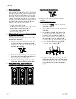
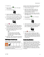
8. Check coolant color.
Use a flashlight to inspect the color of the coolant
through sight glass (SG). The mesh filter should
be visible inside the sight glass and the coolant
should be green. If there are a lot of air bubbles,
then the coolant level may be low. If the coolant
is a milky color, then that indicates A or B material
has likely leaked inside a heat exchanger and
that the coolant needs to be drained.
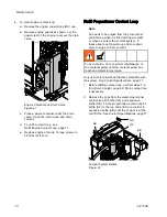
• To add more coolant, see
Refill Proportioner Coolant Loop, page 70 and
Refill Engine Coolant Loop, page 71.
• To drain the coolant system, see
9. Switch on the air compressor, air dryer, breathing
air, and other accessories.
Complete the following steps for systems with a
supplied air compressor.
a. Close the main air shutoff valve, desiccant
air dryer inlet valve, and water drain valve
(CH) whenever the pressure in the air supply
tank has been relieved.
b. Press start on the air compressor power box
(CB). Wait until the pressure gauge (CJ) on
the air supply tank reaches 30 psi.
c. Open the desiccant dryer inlet valve, water
drain valve, and the main air shutoff valve.
10. During initial startup, ensure all three air
regulators are turned fully counterclockwise.
11. Open the main air shutoff valve.
12. Slowly increase the air pressure regulator
settings.
13. Load fluid with feed pumps.
a. Check that all Setup steps are complete.
See Setup, page 33.
b. If an agitator is used, open the agitator’s air
inlet valve.
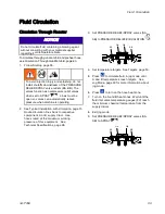
c. If you need to circulate fluid through the
system to preheat the drum supply, see
Circulation Through Reactor, page 59.
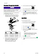
If you need to circulate material through
the heat hose to the gun manifold, see
Circulation Through Gun Manifold, page 60.
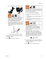
d. Turn both PRESSURE RELIEF/SPRAY
valves (SA, SB) to SPRAY
.
SB
SA
GA
GB
e. Adjust A and B feed pump air regulators to
desired air pressure, on front of proportioner,
to start the feed pumps. Do not exceed 130
psi (0.2 MPa, 2 bar) to the A and B feed
pumps.
56
3A1705E
Содержание 259079
Страница 34: ...Setup A5 A1 A2 AS AN A3 AT A3 A4 A2 A6 A4 34 3A1705E...
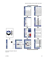
Страница 45: ...Advanced Display Module ADM Operation Setup Screens Navigation Diagram Figure 35 3A1705E 45...
Страница 49: ...Advanced Display Module ADM Operation Run Screens Navigation Diagram Figure 36 3A1705E 49...
Страница 93: ...Dimensions Dimensions Top View Figure 43 Side View Figure 44 3A1705E 93...
Страница 95: ...Dimensions Pallet Mounting Dimensions Figure 48 3A1705E 95...
Страница 97: ...Notes Notes 3A1705E 97...


