27 GMC-I Messtechnik GmbH
8.2.2.
Module Installation
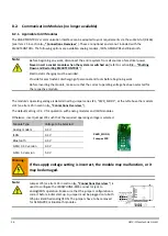
Unpack the new module and make sure that all of the pins are straight. The module is inserted into the socket
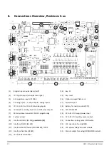
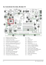
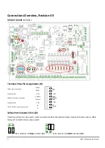
provided to this end [see item 25 in section 6. , “Connections Overview,”].
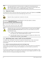
Tip:
If a previously inserted modules needs to be removed, pull it out carefully. Grip the module at the
left and right-hand sides with both hands underneath the PCB, and pull it out slowly and carefully.
The module must not be tilted during removal.
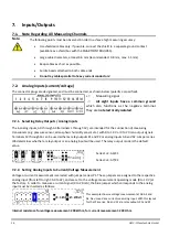
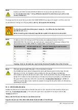
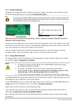
Jack A in the socket, identified with a white arrow, serves as a point of orientation on the PCB. The point of
orientation on the module is pin A.
Carefully insert the module. Pin A on the module must be inserted into jack A at the socket. Make sure that all of
the other pins are also inserted in to their corresponding jacks. (Depending upon the type of module, some of the
pins in the middle portion of the module might not be connected.)
Grasp the module at the sides of the PCB with both hands and push it into the socket carefully and evenly,
avoiding any tilting. Inspect the module to make sure that none of the pins have been bent.
8.2.3.
Analog-Modem Module
The analog module is inserted at the factory as standard equipment. Please check the condition of the module.
See also section 8.2.1. , “Applicable to All Modules”.
For SMARTCONTROL IP 65: Feed the RJ11 plug at the end of the modem’s connector cable into the box via one of
the cable glands. Lay the cable into the cable duct in the box.
For all SMARTCONTROL versions: Insert the RJ11 plug on the connector cable into the ISDN/PHONE-RJ45 jack for
analog connection on the PCB [see item 22 in section 6. , “Connections Overview,”]
Plug the other end of the cable into a TAE-N telephone socket.
A reset must then be executed in order to assure that the new setting is transferred to the modem (refer to
section 9.3. , “Shutting Down and Restarting SMARTCONTROL”).
After restarting, make sure that the communication LEDs between the RJ45 jack and the modem blink briefly
several times.
Note:
An analog connection must be available at the SMARTCONTROL. Operation at analog
private branch extensions is possible.
The number of rings before the modem answers a call can be selected with the
SMARTCONTROL Manager. At least 1 must be entered. If no setting is entered, or if the
number of rings is set to 0, the analog modem does not answer at all!
The connection is laid out as an RJ45 jack. Use an RJ11 cable to connect the analog modem!
Socket module from above, pin A
Jack A identified with a
white arrow on the PCB

