11 GMC-I Messtechnik GmbH
Note:
Close proximity to water, sources of heat, direct sunlight, radiators, devices which generate
electromagnetic fields, transmitters, high frequency sources, radiation emitting devices and
locations which are exposed to excessive vibration or shock must be avoided.
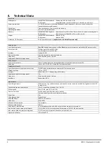
Ambient temperature should lie within a range of +5 and +50°C, and no condensation is allowed.
If these requirements are not fulfilled by the ambient conditions, please install fully encapsulated
devices only.
Note:
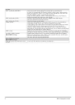
When recording energy data, make sure that the SMARTCONTROL is protected against
manipulation and destruction.
The devices are not intended for use in explosion-proof zones.
Observe additional information included section 3. , “General Safety Precautions” and section 4. , “Technical
Data”.
5.3.
Wall Mounting
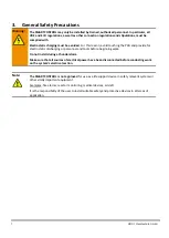
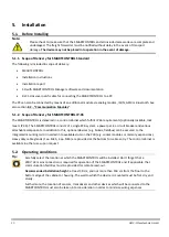
Warning:
Before drilling holes, make sure that there are no cables, pipes or other lines which have been
laid inside the wall in close proximity to the intended installation position.
5.3.1.
Wall Mounting the SMARTCONTROL Standard
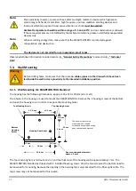
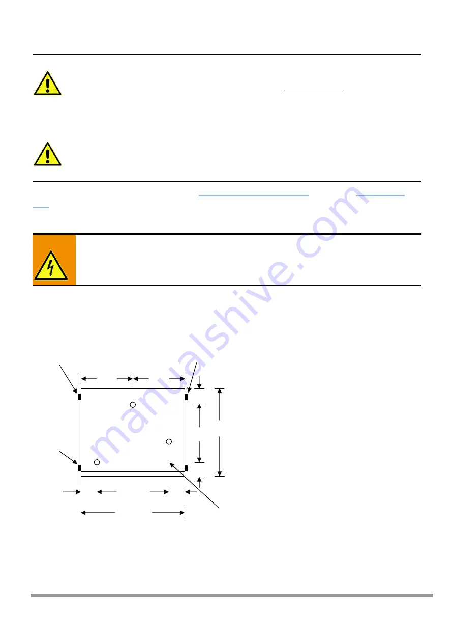
The housing has the following dimensions: approx. 226 x 210 x 70 mm (W x H x D).
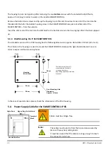
The 3 holes in the housing are used to mount the SMARTCONTROL. Remove the 2 housing screws at the bottom
and open the housing cover in order to expose the mounting holes.
The top mounting hole is laid out as a slot, and the thickness of the housing wall is approximately 1 mm. The
SMARTCONTROL Standard is shipped with 4 installed housing screws. Only the two screws at the bottom need to
be loosened for mounting, because the opening in the housing top is only intended for the fiber-optic cable. The
top screws may not be loosened for this reason.
22.6 cm
16 cm
21 cm
The box must be securely
mounted with 3 suitable
screws and anchors, depending
upon substrate and material.
Housing Rear Panel
11.3 cm
11.3 cm
16 cm
Box mounting tab diameter:
approx. 5 mm
3.3 cm
3.3 cm
2.6 cm
Top Housing Screw
Top Housing Screw
Bottom
Housing
Screw


