1 0991 483
EN
-
21.12.2011
ENG
1.05
24 / 46
NGV A3
VALVE
M
ANUAL
I
NSTALLATION
, U
SE AND
M
AINTENANCE
3.5 DECELERATION DISTANCES
ON
UP
DN
OFF
V
2
V
S
M
P
V
1
V
0
V
0
V
1
D
V
2
1s
D
R
A
L,
D
D
R
A
L,
S
V
N
[m/s]
D
RAL,S
[m]
Upward
Extra Slow
Slow
Standard
Fast
0,00 < V
≤
0,15
0,19
0,15
0,13
0,12
0,15 < V
≤
0,40
0,43
0,39
0,37
0,32
0,40 < V
≤
0,65
0,81
0,71
0,63
0,61
0,65 < V
≤
0,85
1,16
0,99
0,92
0,89
0,85 < V
≤
1,00
1,40
1,27
1,17
1,10
V
N
[m/s]
D
RAL,D
[m]
Downward
Extra Slow
Slow
Standard
Fast
0,00 < V
≤
0,15
0,15
0,13
0,12
0,12
0,15 < V
≤
0,40
0,41
0,36
0,34
0,31
0,40 < V
≤
0,65
0,78
0,67
0,62
0,58
0,65 < V
≤
0,85
1,14
0,98
0,88
0,83
0,85 < V
≤
1,00
1,36
1,18
1,11
1,05
EXTRA SLOW
SLOW
STANDARD
FAST
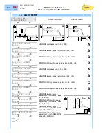
The distance between the deceleration sensor (D
RAL
) and the floor must be regulated according to the chart
above. If the levelling space is greater is possible to make an adjustment using the programmer as shown in
the chapter
Programming
.
D
Downward command
ON
Powered
DN
Downward
UP
Upward
M, MP
Motor / pump
V0, V1, V2
Speed (high, medium, inspection)
OFF
Not powered
VS
Upward command


