1 0991 483
EN
-
21.12.2011
ENG
1.05
8 / 46
NGV A3
VALVE
M
ANUAL
I
NSTALLATION
, U
SE AND
M
AINTENANCE
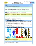
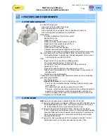
1.3 HOW THE NGV A3 WORKS
The valve NGV is made with a non-return valve VR, a control spool VB controlled by a stepping motor and by
a system with pilot operated non-return valve VRP - P
(moved in opening by the electro-valve VMD)
Valve VR
It is a valve that prevent , during the downward, the oil inlet to the pump.
It forces the oil that comes from the VRP C2 to pass through the spool VB and then in the
C3 and in the tank T1.
Valve VRP-P
It is the pilot operated non-return valve, requested by rules.
During upward the valve works only as ON/OFF, the spool VRP opens or closes
depending on the oil that comes. Its position is determined by the ratio between the
pressure that develops in the chamber C2 and the one that occurs in chamber C1
During downward, instead, it opens the oil way to the valve block (chamber C2).
Its opening is made by the pushing of the piston P that is opened by the pilot operated
valve VMD
Spool VB
It’s the main part of the control block.
It adjusts the oil quantity that should be discharged and determines all the movements of
the car
Its movement is controlled by a stepping motor coupled to the spool VB, through a screw-
nut coupling (necessary to transform the rotatory motion into translatory).
The spool adjusts both the upward phase (with a direct control of the oil that should be
discharged and, indirectly the oil for the cylinder) than that of downward (directly)
All the other valves have features of safety, pilotage, etc. For example :
MPS+OPP
Maximum pressure valve with pilot
5
Overspeed screw
VSMA
Emergency lovering valve
S1
S3
VMD
J
VB
VSMA
3
PT
FLT
VR
P
C4
C2
S2
C1
M1
OPP
MPS
C3
T1
VRP
5
BH BL S
50 5152
V- VSV0 V1 V2 V3 V+
A+PE A- A-
D+ D- E+ E-
1
3
NGV-A3-01
EXP
VMD
D- E+ E-
11 12 21 22 31 32 41 42
X14
X15
X12
X11
X10
X9
X8
X7
X13
A-
+ -
T+ T- P+ P-
+ -
+ -
X1
X3
X4
X6
X5
X2
J2
J3
J6
J1
1
3
1
3
SM


