1 0991 483
EN
-
21.12.2011
NGV A3
VALVE
M
ANUAL
I
NSTALLATION
, U
SE AND
M
AINTENANCE
31 / 46
1.05
ENG
5 PROGRAMMING
It is possible to dialog with the NGV01 control board by the programmer PT01.
The connection between the programmer and the board is made by a network UTP RJ45 straight cable.
The programmer power supply comes from the control board through the connection cable.
It is possible to navigate into the menus and change the numeric values using the arrow keys
Ý
Þ
, it is
possible to enter into the sub-menus and confirm the input data by the ENT key and finally it’s possible exit
and move the cursor left side by the ESC key.
Network cord UTP RJ45
WARNING
MIN
= Car empty
MAX
= Car with full
load
BH BL S
50 51 52
V- VSV0 V1 V2 V3 V+
A+PEA- A-
D+ D- E+ E-
1
3
NGV-A3-01
EXP
VMD
D- E+ E-
11 12 21 22 31 32 41 42
X14
X15
X12
X11
X10
X9
X8
X7
X13
A-
+ -
T+ T- P+ P-
+ -
+ -
X1
X3
X4
X6
X5
X2
J2
J3
J6
J1
1
3
1
3
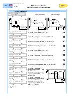
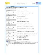
5.1 SYSTEM PARAMETERS
NOTE
It is recommended to indicate in the table below the parameters of your system
To write your parameters make easy future maintenance and repairs.
4
ADJUSTMENTS
6
UP PARAMETERS
4.1
Start UP min
6.2
Int. Speed V1
4.2
Slow UP min
6.3
Ins.Speed V2
4.3
High DN min
6.4
Slow Speed
4.4
Slow DN min
6.5
Relev. Speed
4.5
Start UP max
6.6
Acc.Profile
4.6
Slow UP max
6.7
Dec.Profile
4.7
High DN max
6.8
Start Delay
4.8
Slow DN max
7
DN PARAMETERS
4.9
Offset V0 UP
7.1
Nom. Speed V0
4.10 Offset V0 DN
7.2
Int.Speed V1
4.11 Offset V1 UP
7.3
Insp. Speed V2
4.12 Offset V1 DN
7.4
Slow Speed
5
SETTING
7.5
Relev. Speed
5.1
Lift Ratio
7.6
Acc.Profile
5.2
Jack Diam
7.7
Dec.Profile
5.3
Pump Flow
8
OUTPUT FUNC
5.5
Pstat. min
8.1
Output 11-12
5.6
Pstat.max
8.2
Output 21-22
8.3
Output 31-32
8.4
Output 41-42


