1 0991 483
EN
-
21.12.2011
NGV A3
VALVE
M
ANUAL
I
NSTALLATION
, U
SE AND
M
AINTENANCE
17 / 46
1.05
ENG
2.8 CONNECTION OF HYDRAULIC PIPES
ñ
8 ÷ 36
3/4" x 3/4"
3/4"
-
3/4" x 3/4"
3/4"
42 ÷ 52
3/4"
3/4"
3/4" x M36"
-
3/4" x M36
55 ÷ 100
1” x M36
1”
-
1” x M36
1”
100 ÷ 150
1”
1” x M45
1” x M45
180 ÷ 216
1”1/4
-
1”1/4 x M45
1”1/4
35
1”1/4 x M45
1”1/4
250 ÷ 300
1”1/4
1”1/4
1”1/4GM x 1”1/2GF
+ 1”1/2 x M52
360 ÷ 432
1”1/2
1”1/2 x M52
1”1/2
42
1”1/2 x M52
1”1/2
500 ÷ 600
1”1/2
-
2”
2” x 2”
2”
-
2” x 2”
2”
2.8.1 CONNECTION WITH FLEXIBLE HOSE
·
Remove the gear and the cutting ring from the terminal
connection of the silencer.
·
Ensure that the terminal connection is well fixed on the
silencer.
·
Clean and oil the threading and their seats.
·
Fix the flexible hose verifying it is thoroughly tightened.
WARNING
Ensure that there is no dirty inside the tube. These
impurities could damage the sealing of the piston and of
the valve block and inhibit the correct operation of the
system.
2.8.2 CONNECTION WITH A RIGID PIPE
·
Cut at 90° the head of the tube with a saw (do not use a tube-cutter)
·
Do not let metal residuals fall into the tube and eliminate the burrs internally and externally.
·
Remove the gear and the cutting ring of the terminal connection and insert it on the pipe.
·
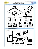
Ensure that the cutting ring is inserted as indicated in image
·
Ensure that the terminal connection is well fixed on the silencer.
·
Clean and lubricate the threading and the connection seat with
a slight oil veil.
·
Insert the pipe into the cone at 24° up to lay it on the stop limit
of the cone itself.
·
Screw thoroughly the gear by hand until it is felt that the cutting
gear lays perfectly to the nut.
·
Then screw the nut using a wrench until the cutting edge of the
ring is in contact with the tube and prevents it from rotating.
·
Keep the tube against its stop to avoid it rotates, screw the
fixing nut by 3/4 rev. In doing so the ring engraves with the
necessary depth the external part of the tube and rises a
border in front of its cutting edge.
·
Loose the nut and check that the tube has all around a well
risen border. The border must cover 70% of the front part of
the cutting ring.
·
Fix the tube, close the nut with a wrench until a certain
resistance is felt; from this moment on screw for a further 1/4
turn, contrasting wrench against wrench.
WARNING
Ensure that there is no dirty inside the tube. These impurities could damage the sealing of the piston
and of the valve block and inhibit the correct operation of the plant.


