background image

Supplied By www.heating spares.co  Tel. 0161 620 6677

49

220692C

49

SECTION

12

Replacement of Parts

Main Burner

Main Burner Injector

Gain access as Section 10, steps 1 to 5 and 9.

Remove burner as in Section 10, step 13.

Gain access as Section 10, steps 1 to 5 and 9.

Remove the injector as in Section 10, steps 13 and 14.
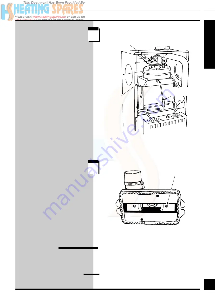
Fan

Gain access as Section 10, steps 1, 2
and 5.

Remove the electrical connections and
disconnect the air tubes.

Remove the fluehood/fan assembly
screws and withdraw the assembly.

Turn the flue hood over and release the
two securing screws as shown.

Remove the sealant from the fan outlet
and manifold.

Take the beige/grey sealant supplied
with the replacement fan and place
firmly around the internal spigot of the
flue manifold.

After fitting the fan outlet to the spigot
smooth the sealant over the joint.

Make sure that when fitting the
replacement fan to the flue hood that it
is the correct way round for connection
to the flue, refer to the diagram in
Section 6, also steps 10 and 11.

Make sure  that the earth connection
is remade onto the new fan assembly.

The polarity of the other connections is
not important.

3058

SECURING
SCREW (2)

FAN/FLUEHOOD
SCREW (2)

AIR PRESSURE
SWITCH TUBES

ELECTRICAL
CONNECTIONS

s t e p

1

s t e p

2

EARTH

CONNECTION

Содержание Space Saver K.F.B 60

Страница 1: ...73 824141 Fax 01773 820569 One Contact Local Service Customer Services Tel 01773 828100 Fax 01773 828070 This is a Cat I2H Appliance BS 6332 BS 5258 Fully Pumped system Open Vented or Sealed Fanned Fl...

Страница 2: ...may be susceptible to irritation High dust levels are usual only if the material is broken Normal handling should not cause discomfort but follow normal good hygiene and wash your hands before eating...

Страница 3: ...Standard exists materials and equipment should be fit for their purpose and of suitable quality and workmanship This boiler must have fully pumped circuits but is suitable for use with open vented or...

Страница 4: ...requirements B S I Certification The boiler is certificated to the current issue of BS6332 Part 1 invoking the current issue of BS5258 Part 1 for performance and safety It is therefore important that...

Страница 5: ...ure max Space Saver Space Saver Range Rating K F B K F B 60 70 Btu h 70064 84416 kW 20 54 24 74 Btu h 75000 89709 kW 21 98 26 29 Btu h 64935 78947 kW 19 03 23 14 Data Label Position 3038 Space Saver S...

Страница 6: ...h a common isolator and must be fused 3A maximum The method of connection should be preferably an unswitched shuttered socket outlet and 3 pin plug both to the current issue of BS1363 Alternatively a...

Страница 7: ...the boiler whether or not adding an inhibitor 2 Water Systems Bypass Inhibitor Notes Open Vented and Sealed Water Systems Pump See chart for pressure drop of the boiler The pump should be fitted in th...

Страница 8: ...150mm MAX FLOW RET RET CYLINDER FLOW HEATING Open Vented Water System For an open vented system the boiler must be supplied from an unrestricted water supply taken from a feed and expansion cistern s...

Страница 9: ...out unless laid down differently by the manufacturer The expansion vessel volume depends on the total water system volume and the initial system design pressure For any system an accurate calculation...

Страница 10: ...0 to 4bar 0 to 60lb in2 shall be fitted permanently to the system in a position where it can be seen when filling the system Domestic Hot Water Cylinder SINGLE FEED INDIRECT CYLINDERS ARE NOT SUITABLE...

Страница 11: ...of BS7671 with respect to the installation of a boiler in a room containing a bath or shower Any electrical switch or boiler control using mains electricity should be so situated that it cannot be tou...

Страница 12: ...ation of the boiler will be in an unusual location special procedures are necessary refer to the current issue of BS6798 for guidance A compartment used to enclose the boiler must be designed and cons...

Страница 13: ...xternal air It is important that the position of the terminal allows the free passage of air across it at all times Terminal Position The minimum acceptable spacings from the terminal to obstructions...

Страница 14: ...UE APPLICATION LENGTH AND TERMINAL POSITION BEFORE PROCEEDING Refer to the relevant diagrams in Section 4 For wall thickness of less than 300mm the boiler can be fully installed from inside For a wall...

Страница 15: ...ll face If the inner end of the sleeve sticks out into a cavity then if desired the wall sleeve can be trimmed back to the depth of the inner skin of the brickwork Make good at the internal wall face...

Страница 16: ...2893 s t e p s t e p 4 5 s t e p 1 1 Continue at Flue Duct Standard or Long Mark the duct to the length Q 11mm then cut square and remove any burrs Air Duct Terminal Standard or Long Mark the duct to...

Страница 17: ...and extend the flue horizontal centre line to the corner of the adjacent surface Mark out and cut the hole for the flue using preferably a 115mm minimum core drill If the wall thickness Q is less tha...

Страница 18: ...E TEMPLATE Flue Duct Standard or Long Mark the duct to length S 11mm then cut square and remove any burrs Terminal Air Duct Standard or Long Mark the duct to the length S 13mm then cut square and remo...

Страница 19: ...y Locate the flue duct into the air duct terminal Place the sealant from the loose items pack onto the flue manifold Fully locate the flue manifold into the air duct terminal and flue duct assembly as...

Страница 20: ...oiler is not to be fitted for sometime cover the hole in the wall On all installations push the flue assembly into and through the wall sleeve and hole such that it is within the wall sleeve and does...

Страница 21: ...on Remove the front panel and place it on one side until required Remove and discard internal packing piece Remove the inner case by releasing the screws at the bottom and unhooking at the top place o...

Страница 22: ...3 5 6 7 8 and 9 Lift the boiler into position above the top mounting bracket allow the boiler to slide down the wall onto the top and bottom wall mounting brackets Check the engagement by pulling the...

Страница 23: ...o the heat exchanger with the screws previously removed If removed refit the control box combustion chamber by reversing the instructions in Section 6 step 18 and Section 10 steps 3 5 6 7 8 and 9 Reco...

Страница 24: ...ssembly to the required flue outlet direction Fit the flue hood over the partially fitted securing screws in the special key hole slot sandwiching the gaskets and spacer between take care not to damag...

Страница 25: ...10 steps 3 5 6 7 8 and 9 Lift the boiler into position above the top mounting bracket allow the boiler to slide down the wall onto the top and bottom wall mounting brackets Check the engagement by pul...

Страница 26: ...extended brass fluehood fan assembly screw to the heat exchanger on the side that the flue exits Slide the fluehood fan assembly flange under this extended brass screw whilst turning the assembly to...

Страница 27: ...gs provided in the loose items pack The flow connection is on the right Gas Supply Connection Remove the electrical controls box cover Connect the gas supply to the gas service cock on the boiler maki...

Страница 28: ...ols cables through the restraining glands The earth conductor must be of a greater length so that if the cable is strained the earth is the last to become disconnected Test the insulation resistance o...

Страница 29: ...ease cold water to initial system design pressure The set pointer on the pressure gauge should be set to the initial design pressure If air is present in the system this may in certain circumstances c...

Страница 30: ...tor slot to be horizontal The pilot gas rate is preset and MUST NOT be adjusted see Servicing Step 15 For future reference stick the self adhesive arrow indicator from the loose items pack to the data...

Страница 31: ...e electrical supply to the boiler and test the polarity of the mains supply Turn the boiler thermostat knob fully clockwise to the maximum setting The lighting sequence is automatic as follows The fan...

Страница 32: ...pliances and pilot lights are off Space Saver K F B 60 Approx Gas Rate min med max m3 h 1 8 1 95 2 1 ft3 h 64 69 74 Space Saver K F B 70 Approx Gas Rate min med max m3 h 2 2 2 4 2 5 ft3 h 78 83 89 The...

Страница 33: ...em should then be balanced adjusting the pump and lockshield valve as necessary Having achieved a satisfactory condition operate the boiler with the bypass closed on minimum load normally central heat...

Страница 34: ...m 315mm deep and will also suit installations in a cupboard It is delivered preset to 700mm high by 285mm deep Measure the height of the cupboard or compartment H Adjust the front panel height H as ne...

Страница 35: ...eing out of use during frost and freezing conditions Advise the user to ensure the continued efficient and safe operation of the boiler it is recommended that it is checked and serviced as necessary a...

Страница 36: ...NDICATOR SLOT TO BE VERTICAL Unless stated otherwise all parts are replaced in the reverse order to removal After completing any servicing always test for gas soundness and if necessary carry out func...

Страница 37: ...xchanger Slacken the flue hood by loosening the extended brass screws at the left and right hand sides Remove the split pin and thermostat phials from the pocket taking care not to kink the capillarie...

Страница 38: ...rical control box combustion chamber cover assembly by removing the ten securing screws withdraw the complete assembly Slacken the air pressure pipe union and turn through 90o Remove the rear flueway...

Страница 39: ...nger front cover Tighten down the fan flue screws Refit the cleaning plate Main Burner Remove the main burner by releasing the two securing nuts as shown Brush or vacuum away any deposits ensure that...

Страница 40: ...ends releasing the pilot pipe Remove the pilot burner securing screws to release the pilot burner and electrode assembly Clean the pilot burner and electrode Remove the pilot injector by unscrewing it...

Страница 41: ...he overheat device may need resetting Remove the front panel as Section 1 Step 1 and press the reset button on top of the electrical controls box cover see diagram at Step 3 If the cut off operates at...

Страница 42: ...SIS EARTH POST CHASSIS EARTH CONTROL THERMOSTAT Remove RED link between 7 and 12 when fitting a time control etc If no switch is fitted the pump will run continuously E N L N L E 12 11 10 9 8 7 6 5 NC...

Страница 43: ...PCB Is neon 1 lit Fault with mains supply or PCB fuse Overheat cut off device tripped or thermostat overheat cut off device faulty see detailed fault finding chart Air flow proving fault that is fan o...

Страница 44: ...ode lead connection for poor contact Check electrical supply polarity and correct if necessary If satisfactory replace printed circuit board Isolate supply test harness continuity If satisfactory repl...

Страница 45: ...run will keep the pump running to allow the boiler to cool down after which it will stop providing the remote controls are NOT calling for heat Turn off remote controls does the pump stop after a shor...

Страница 46: ...h connector Disconnect the three electrical plugs ignition lead the earth and mains cables Pull the board away from the supports When fitting the replacement make sure that it is correctly located on...

Страница 47: ...it pin and then the thermostat phials from the pocket Make sure that the thermostat capillaries are correctly routed and the phials are securely fitted into the pocket Note The position of the two phi...

Страница 48: ...Undo the four screws at the outlet manifold and disconnect the gas service cock union Transfer the half union of the gas service cock to the inlet of the replacement gas valve Also transfer the pilot...

Страница 49: ...the two securing screws as shown Remove the sealant from the fan outlet and manifold Take the beige grey sealant supplied with the replacement fan and place firmly around the internal spigot of the fl...

Страница 50: ...ve the baffles Remove the insulation and fit the replacement parts making sure they are fitted as shown s t e p 1 s t e p 2 Heat Exchanger Front Cover Panel Remove panel Section 10 step 10 Upper Insul...

Страница 51: ...Gas valve assembly inc item11 313 300 2 202539 Thermostat 397 893 3 202538 Overheat thermostat 397 894 4 900817 Printed circuit board 313 301 5 440073 Fan assembly 60 special 397 987 5 800238 Fan ass...

Страница 52: ...Supplied By www heating spares co Tel 0161 620 6677 52 220692C 52 SECTION Because of our constant endeavour for improvement details may vary slightly from those given in these instructions...

Отзывы: