Location
31
Code no. 550038
Rev. no. 16/1018
3.4.2. Ventilation openings. Models with gas heating
The air must be supplied through openings in the walls of the
premises in direct contact with the outside air.
These openings must be protected to prevent entry of water
or foreign bodies.
Refer to extraction flow in Chapter 4:
Technical and
connection data for the machine
(
EV
value).
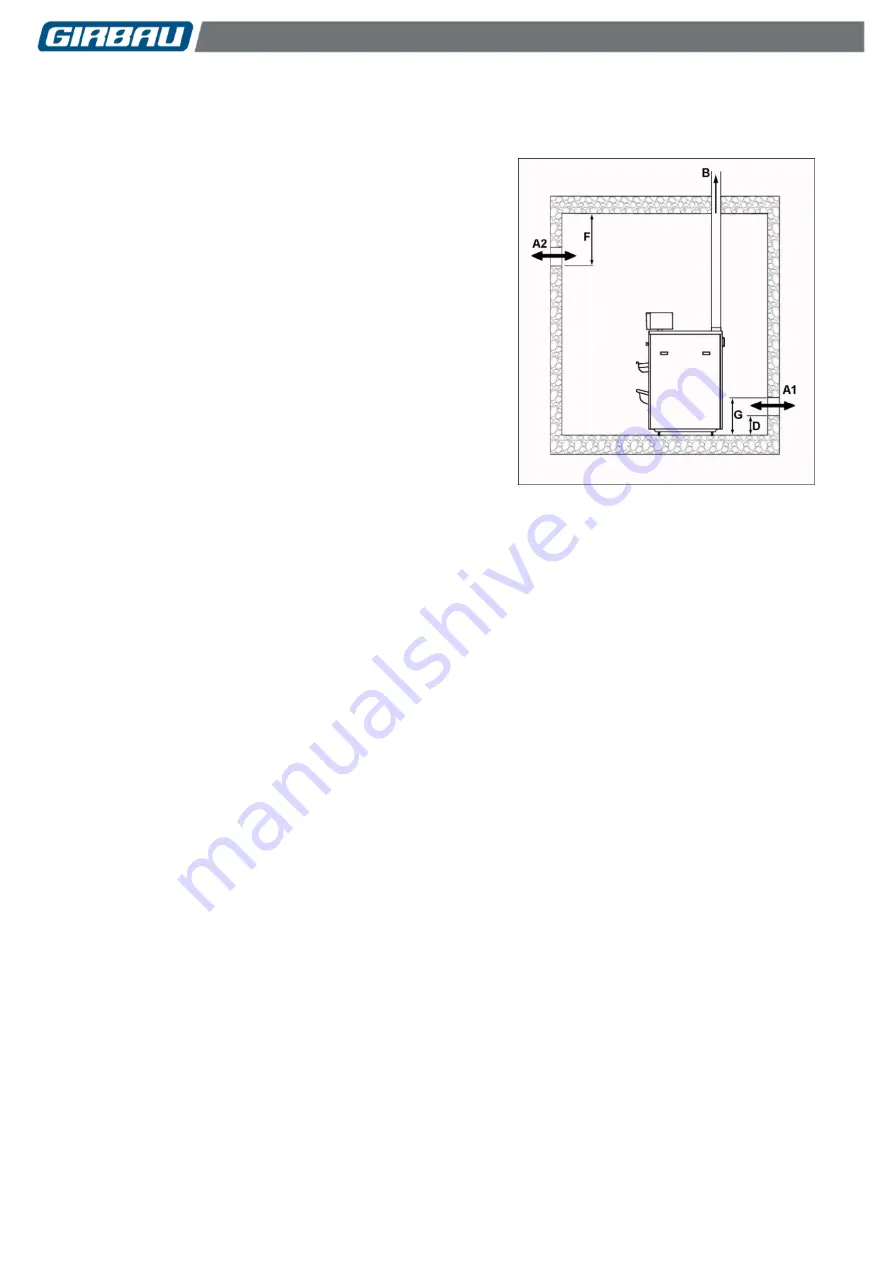
Figure 3.3.
Two openings communicating with the outside are
recommended: one located at the top of the premises
(A2)
and another at the bottom
(A1)
, close to the machine. It is
advisable to create the openings in opposite walls.
In the case of rectangular air openings, the longest side must
not be more than double the length of the smaller side.
The machine’s exhaust duct
(B)
should always lead directly
to a secure outside location and never be connected to any
other duct or flue.
Fig. 3.3
Size of the A1 and A2 openings
The minimum free surface area of the openings
(Si)
should be 5 cm2 (0.75 sq.in) per kW of nominal
heat consumption (referred to as Hs) installed.
The minimum area of each of the openings should never be less than 250 cm2 (37.5 sq.in).
In openings protected with protective grilles, the free surface of the opening must be equal to or greater
than the minimum area indicated.
Position of the openings:
Bottom opening (A1)
:
The bottom edge should be at a height (
D
) of less than or equal to 15 cm (5.9 in) from the floor of the
premises.
The top edge should be at a height (
G
) of less than or equal to 50 cm (20 in) from the floor of the
premises.
Top opening (A2)
:
The bottom of the opening should be at a maximum distance (
F
) of 30 cm (11.8 in) from the ceiling.
Содержание PB32 Series
Страница 52: ...Technical data 52 Code no 550038 Rev no 16 1018 4 9 2 PB PBP51 X20 models Fig 4 3 ...
Страница 98: ...Operating and use Inteli Control 98 Code no 550038 Rev no 16 1018 MANUAL MODE AUTOMATIC MODE ...
Страница 114: ...Operating and use Logi Control 114 Code no 550038 Rev no 16 1018 8 5 2 Advanced mode flowchart ...


