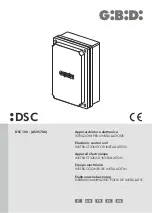
DSC100
8
UK
UK
PRODUCT DESCRIPTION
FEATURES / FUNCTION
The electronic board AS05780 can manage an electromagnet used as accessory on a sliding gate to make the
system reversible or irreversible.
• Jumper to select installation type.
Possibility of using a limit switch to keep the gate locked in opening.
Automatic functioning at the power on or after a proper command.
Possibility of using the flashing light signal 12/24 Vdc or 230 Vac to activate the functioning cycle
•
•
•
CONTROL UNIT
DSC100 / AS05780
Type
Power supply
Electromagnet power supply
Electromagnet voltage maintenance
Electromagnet power
Relay contact
Operating temperature
Electronic board for electromagnet management
230 Vac, single-phase, 50/60 Hz
24 Vdc
12 Vdc
50 VA
250 Vac 16 A
-20°C +60°C
INSTALLATION WARNINGS
• Before proceeding with the installation, fit a magnetothermal or differential switch with a maximum capacity of 10°
upstream of the system. The switch must guarantee omnipolar separation of the contacts with an opening distance
of at least 3 mm.
To prevent possible interference, differenziate and always keep the power cables (minimum cross-section
1.5 mm²) separate from the signal cables (minimum cross-section 0,5mm²).
Make the connections referring to the following tables and to the attached silkscreen. Be extremely careful to
connect in series all the devices that are connected to the same N.C. (normally closed) input, and in parallel all the
devices that share the same N.O. (normally open) input. Incorrect installation or improper use of the product may
compromise system safety.
Keep all the materials container in the packaging away from children since they pose a potential risk.
The manufacturer declines all responsibility for improper functioning of the automated device if the original
components and accessories suitable for the specific application are not used.
After installation, always check carefully proper functioning of the system and the devices used.
This instruction manual addresses people qualified for installation of “live equipment”. Therefore, good technical
knowledge and professional practice in compliance with the regulations in force are required.
Maintenance must be carried out by qualified personnel.
Before carrying out any cleaning or maintenance operation, disconnect the control unit from the mains.
This control unit may only be used for the purpose for which it was designed. Check the aim of the final use and
make sure that all safety measures are taken.
Use of the product for purposes different from the intended use has not been tested by the manufacturer, therefore
any work is carried out on full responsibility of the installer.
Mark the automated device with visibile warning plates.
Warn the user that children or animals may not play or stand around near the gate.
Appropiately protect the dangerous points (for example, using a sensitive frame).
•
•
•
•
•
•
•
•
•
•
•
•
•
DSC100
9
WARNINGS FOR THE USER
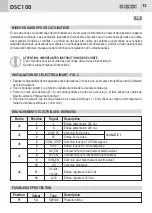
ELECTROMAGNET INSTALLATION - FIG. 2
In the event of an operating fault or failure, cut the power upstream of the control unit and call Technical Service.
Periodically check functioning of the safety devices. Any repairs must be carried out by specialised personnel using
original and certified materials. The appliance is not to be used by children or people with reduced physical, sensory
or mental capabilities, or lack of experience and knowledge, unless they have been given supervision or instruction.
Do not access the control board for settings and / or maintenance.
1. Remove the unlocking body after having unscrewed the 2 Allen screws. The same holes M6 are used to fix the
electromagnet.
2. Fix the support flange (1) to the gearmotor body by means of the countersunk head screw (A).
3. Drill the gearmotor body (Ø = 6) in correspondence to the hole inside the slotted hole (2) and run the electromagnet
cables through the gearmotor body.
4. Fix the electromagnet (3) to the flange with the cylyindrical head screw L = 16 mm (B) and to the gearmotor body by
means of the cylindrical head screw L = 30 mm (C)
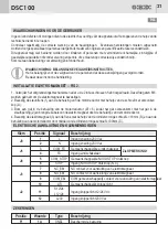
ELECTRICAL CONNECTIONS: TERMINAL BLOCKS
Terminal
Position
Signal
Description
J9
J5
See NOTE 1
J8
J3
J2
1
2
3
4
5
6
7
8
9
10
11
12
L
N
COM_FC
FC
COM_STOP
STOP
NC_EM
NO_EM
COM_EM
L/S
S12/24
L12/24
L230
Power input 230 Vac
Power input 230 Vac
Common limit switch
Limit switch input
Common emergency STOP push button
Emergency STOP push button input
NC contact for electromagnet connection
NO contact for electromagnet connection
Common contact for electromagnet connection
Common flashing light
Flashing light input 12/24 Vdc
Flashing light input 230 Vac
PROTECTION FUSES
Position
Value
Type
Description
F1
1 A
FAST
Electronic board protection
WARNING: IMPORTANT SAFETY INSTRUCTIONS
It is very important to follow the present instructions for your own safety.
Please keep this manual

