background image

DSC100

6

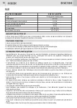
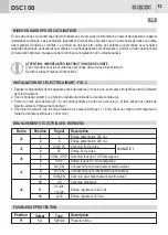
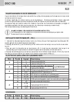
IMPOSTAZIONI - JUMPER SW1

IMPOSTAZIONE DI DEFAULT

Jumper

SW1

Posizione

ON

Stato

Funzione

Descrizione

SW1

ON

OFF

IMPIANTO

IRREVERSIBILE

IMPIANTO

REVERSIBILE

Vedere paragrafo dedicato

Vedere paragrafo dedicato

FUNZIONAMENTO DEL PRODOTTTO

Collegare l'elettromagnete tra i morsetti 8 e 9. In assenza di alimentazione 230 Vac il cancello è libero di muoversi. 
Quando la centrale DSC100 viene alimentata si hanno le seguenti possibilità.

IMPIANTO IRREVERSIBILE (SW1 = ON)

All'alimentazione della centrale DSC100 l'elettromagnete si attiva bloccando il motore e rendendo quindi l'impianto 
irreversibile. L'elettromagnete resterà attivo fino a quando sarà presente la tensione di alimentazione centrale. 
E' possibile collegare all'ingresso STOP un pulsante con riarmo.
La pressione del tasto STOP disattiverà l'elettromagnete rendendo l'impianto reversibile.
Per riattivare l'elettromagnete sarà necessario riarmare il pulsante STOP. 

In questa modalità l'ingresso FC non è attivo

IMPIANTO REVERSIBILE (SW1 = OFF)

E' necessario abilitare la funzione PRELAMPEGGIO sulla centrale che comanda il motoriduttore.

All'alimentazione della centrale DSC100 l'elettromagnete rimane disattivato lasciando l'impianto reversibile.
L'attivazione  dell'elettromagnete,  con  conseguente  blocco  del  motore  e  impianto  irreversibile,  si  avrà  solo  in 
conseguenza alla presenza del segnale del lampeggiatore proveniente dalla centrale di comando del motoriduttore.

L'elettromagnete rimarrà attivo fin quando sarà presente il segnale del lampeggiatore e si disattiverà 1 s dopo la 
scomparsa del segnale.
In questo modo l'elettromagnete si disattiverà sia quando il cancello è in pausa (fase apertura completata) che 
quando il cancello è a riposo (fase chiusura completata)

Sarà  comunque  possibile  mantenere  il  cancello  bloccato  in  apertura  e/o  chiusura  installando  un  finecorsa  e 
utilizzando l'ingresso FC. Fare attenzione a fare intervenire il finecorsa prima della fine del moto del cancello.

NOTA  1

:  Il  finecorsa  da  collegare  agli  ingressi  3  e  4  NON  è  il  finecorsa  che  comanda  l'arresto  del  motore.

E' un dispositivo supplementare che si deve attivare prima dell'attivazione del finecorsa che blocca il cancello.

DSC100

7

IT

IT

AVVERTENZE: 

Questo prodotto è stato collaudato in GI.BI.DI. verificando la perfetta corrispondenza delle caratteristiche alle direttive vigenti.

GI.BI.DI. S.r.l. dichiara

 che i prodotti, a cui questo libretto fa riferimento, sono conformi ai requisiti essenziali delle DIRETTIVE EMC 2004/108/CE 

e LVD 2006/95/CE. La dichiarazione completa è disponibile sul sito www.gibidi.com 

SMALTIMENTO: 

GI.BI.DI. consiglia di riciclare i componenti in plastica e di smaltire in appositi centri abilitati i componenti elettronici evitando 

di contaminare l'ambiente con sostanze inquinanti.

LEGGERE ATTENTAMENTE QUESTO MANUALE PRIMA DI PROCEDERE ALL’INSTALLAZIONE.

Grazie per avere scelto GIBIDI.

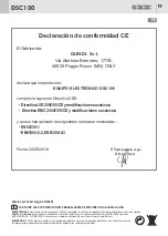
Dichiarazione di conformità CE

Il fabbricante:                

GI.BI.DI. 

Via Abetone Brennero, 177/B,

46025 Poggio Rusco (MN) ITALY

dichiara che i prodotti:

APPARECCHIATURA ELETTRONICA DSC100

sono conformi alle seguenti Direttive CEE:

• 

Direttiva LVD 2006/95/CE  e successive modifiche

;

• 

Direttiva EMC 2004/108/CE e successive modifiche

;

e che sono state applicate le seguenti norme armonizzate:

• 

EN60335-1,

• 

EN61000-6-2, EN61000-6-3

Data 24/09/2018                                     

S.r.l.

Il Rappresentante Legale

Michele Prandi

Содержание AS05780

Страница 1: ...ttronica ISTRUZIONI PER L INSTALLAZIONE Electronic control unit INSTRUCTIONS FOR INSTALLATION Appareil électronique INSTRUCTIONS D INSTALLATION Equipo electrónico INSTRUCCIONES DE INSTALACIÓN Elektronische besturing GEBRUIKSAANWIJZING VOOR DE INSTALLATIE ...

Страница 2: ... 2 5 6 3 4 1 2 SC24 SC230 SW1 J3 RL2 RL1 F1 J8 J5 1A 7 8 9 10 11 12 J2 J9 230Vac NEUTRAL N L 230Vac LINE 10 11 12 J2 10 11 12 J2 FC COM FC COM STOP STOP NC EM NO EM COM EM L S L S 12 24 L S 230 LAMP 12 24 LAMP 12 24 LAMP 230 LAMP 230 ...

Страница 3: ...FIG 2A FIG 2B FIG 2C FIG 2D FIG 2E 2 B C 3 DSC100 3 Ø8mm MAX 10mm MAX 1 A ...

Страница 4: ...cnica esercitatacomeprofessioneenelrispettodellenormevigenti Lamanutenzionedeveessereeseguitadapersonalequalificato Prima di eseguire qualsiasi operazione di pulizia o di manutenzione scollegare l apparecchiatura dalle rete di alimentazioneelettrica L apparecchiaturaquidescrittadeveessereutilizzatasoloall usoperilqualeèstataconcepita Verificare loscopo dell utilizzofinaleeassicurarsidiprenderetutt...

Страница 5: ... e far passare i cavi dell elettromagneteall internodelcorporiduttore 4 Fissarel elettromagnete 3 allaflangiamediantelaviteatestacilindricaL 16mm B ealcorpodelmotoriduttore mediantelaviteatestacilindricaL 30mm C IT COLLEGAMENTI ELETTRICI MORSETTIERE Morsetto Posizione Segnale Descrizione J9 J5 Vedere NOTA 1 J8 J3 J2 1 2 3 4 5 6 7 8 9 10 11 12 L N COM_FC FC COM_STOP STOP NC_EM NO_EM COM_EM L S S12 ...

Страница 6: ...ANTOREVERSIBILE SW1 OFF E necessarioabilitarelafunzionePRELAMPEGGIOsullacentralechecomandailmotoriduttore All alimentazionedellacentraleDSC100l elettromagneterimanedisattivatolasciandol impiantoreversibile L attivazione dell elettromagnete con conseguente blocco del motore e impianto irreversibile si avrà solo in conseguenzaallapresenzadelsegnaledellampeggiatoreprovenientedallacentraledicomandodel...

Страница 7: ...e in appositi centri abilitati i componenti elettronici evitando dicontaminarel ambienteconsostanzeinquinanti LEGGERE ATTENTAMENTE QUESTO MANUALE PRIMADI PROCEDEREALL INSTALLAZIONE Grazie per avere scelto GIBIDI Dichiarazione di conformità CE Il fabbricante GI BI DI Via Abetone Brennero 177 B 46025 Poggio Rusco MN ITALY dichiara che i prodotti APPARECCHIATURA ELETTRONICA DSC100 sono conformi alle ...

Страница 8: ...to connect in series all the devices that are connected to the same N C normally closed input and in parallel all the devices that share the same N O normally open input Incorrect installation or improper use of the product may compromisesystemsafety Keepallthematerialscontainerinthepackagingawayfromchildrensincetheyposeapotentialrisk The manufacturer declines all responsibility for improper funct...

Страница 9: ...ondencetotheholeinsidetheslottedhole 2 andruntheelectromagnet cablesthroughthegearmotorbody 4 Fixtheelectromagnet 3 totheflangewiththecylyindricalheadscrewL 16mm B andtothegearmotorbodyby meansofthecylindricalheadscrewL 30mm C ELECTRICAL CONNECTIONS TERMINAL BLOCKS Terminal Position Signal Description J9 J5 See NOTE 1 J8 J3 J2 1 2 3 4 5 6 7 8 9 10 11 12 L N COM_FC FC COM_STOP STOP NC_EM NO_EM COM_...

Страница 10: ...ERSIBLESYSTEM SW1 OFF ItisnecessarytoenablethePRE FLASHINGfunctiononthecontrolboardofthegearmotor PoweringthecontrolunitAS05780theelectromagnetremainsnotactiveleavingthesystemreversible The electromagnet activation with locking of the gearmotor and irreversible system will happen only by a consequenceofthepresenceoftheflashinglightsignalofthegearmotorcontrolunit The electromagnet will remain activ...

Страница 11: ...presentative Michele Prandi DSC100 10 UK WARNINGS ThisproducthasbeentestedinGI BI DI verifyingtheperfectcorrespondenceofthecharacteristicstothecurrentdirective GI BI DI S r l declaresthattheproductstowhichthishandbookreferscomplywiththeessentialrequirementsofthefollowingDIRECTIVES EMC2004 108 CE LVD2006 95 CE Theentiredeclarationisavailableatwww gibidi com DISPOSAL GI BI DI advises recycling the p...

Страница 12: ...nt la même entrée N A normalement ouvert Unemauvaiseinstallationouunemauvaiseutilisationduproduitpeutcompromettrelasécuritédel installation Tous les matériaux présents dans l emballage ne doivent pas être laissés à la portée des enfants car ils peuvent êtredangereux Le constructeur décline toute responsabilité quant au bon fonctionnement de l automation en cas d utilisation de composantsetd access...

Страница 13: ...spondance du trou de la boucle 2 et faire passer les câbles de l électro aimantàl intérieurduréducteur 4 Fixer l électro aimant 3 à la bride à l aide de vis à tête cylindrique L 16 mm B et au corps du motoréducteur à l aidedevisàtêtecylindriqueL 30mm C BRANCHEMENTS ELECTRIQUES BORNIERS Borne Position Signal Description J9 J5 Voir NOTE 1 J8 J3 J2 1 2 3 4 5 6 7 8 9 10 11 12 L N COM_FC FC COM_STOP ST...

Страница 14: ...asactive INSTALLATIONREVERSIBLE SW1 OFF IlfauthabiliterlafonctionPRECLIGNOTEMENTsurlaplatinequicommandelemotoréducteur Al alimentationdelaplatineAS05780l électroaimantrestedésactivélaissantl installationréversible L activation de l électroaimant avec conséquent blocage du moteur et installation irréversible aura lieu seulement enprésencedusignalduclignoteurprovenantdelaplatinedecommandedumotoréduc...

Страница 15: ...MENT CeproduitaététestéchezGI BI DI afindecontrôlerlacorrespondanceparfaitedescaractéristiquesaveclesrèglesenvigueur GI BI DI S r l déclarequelesproduits auxquelsseréfèrelanotice sontconformesauxconditionsessentiellesrequisesparles DIRECTIVES suivantes EMC 2004 108 CE LVD 2006 95 CE La déclaration complète est disponible sur le site www gibidi com ELIMINATION GI BI DI conseille de recycler les com...

Страница 16: ...n paralelo todos los dispositivos que comparten la misma entrada N A normalmente abierta Una incorrecta instalación o utilización del productopuedeafectarlaseguridaddelainstalación Todo material presente en el embalaje debe mantenerse fuera del alcance de los niños ya que consistuye una posiblefuentedepeligro El fabricante declina toda responsabilidad relativa al funcionamiento correcto de la auto...

Страница 17: ... orificio del ojal 2 y hacer pasar los cables del electroimánalinteriordelcuerporeductor 4 Sujetar el electroimán 3 a al brida mediante el tornillo de cabeza cilíndrica L 16 mm B y al cuerpo del motorreductormedianteeltornillodecabezacilíndricaL 30mm C CONEXIONES ELECTRICAS TABLEROS DE BORNES Borne Posición Señal Descripción J9 J5 Ver NOTA 1 J8 J3 J2 1 2 3 4 5 6 7 8 9 10 11 12 L N COM_FC FC COM_ST...

Страница 18: ...IBLE SW1 OFF EsnecesarioactivarlafunciónPREDESTELLOenlacentralquemandaelmotoreductor AlaalimentacióndelacentralAS05780elelectroimánquedadesactivadodejandolainstalaciónreversible La activación del electroimán con consiguiente bloqueo del motor e instalación irreversible se verificará sólo en presenciadelseñaldeldestelladorprovenientedelacentraldemandodelmotoreductor Elelectroimánquedaráactivohastac...

Страница 19: ...o ha sido ensayado en GI BI DI averiguando la perfecta correspondencia de las características a las normas vigentes GI BI DI S r l declara que los productos referidos en este folleto cumplen con los requisitos esenciales de las DIRECTIVAS siguientes EMC 2004 108 CE LVD 2006 95 CE La declaración completa está disponible en el sitio de internet www gibidi com ELIMINACION GI BI DI aconseja reciclar l...

Страница 20: ... De installatie moet uitgevoerd worden door vakmensen diedegeldendevoorschrifteninachtnemen Ÿ Hetonderhoudmoetuitgevoerdwordendoorgekwalificeerdpersoneel Ÿ Alvorens reiniging of onderhoudswerkzaamheden uit te voeren moet de apparatuur van het elektriciteitsnet afgekoppeldworden Ÿ Dehierbeschrevenapparatuurmagalleengebruiktwordenvoorhetgebruikwaarvoorhetontworpenis Ÿ Hetgebruikvandeproductenenhunbe...

Страница 21: ...odat het gat overeenkomt met het gat in de sleufopening 2 enbrengdekabelsvandeelektromagneetdoordebehuizingvandemotorreductor 4 Bevestig de elektromagneet 3 aan de flens met behulp van de cilindervormige schroef L 16 mm B en aan de behuizingvandemotorreductordoormiddelvandecilindervormigeschroefL 30mm C ELEKTRISCHE AANSLUITINGEN KLEMMENBORDEN Klem Positie Signaal Beschrijving J9 J5 Zie OPMERKING 1...

Страница 22: ...SYSTEEM SW1 OFF HetisnodigomdeVOORKNIPPERfunctieopdebesturingvandemotorreductorinteschakelen Bij voeding van de besturing AS05780 de elektromagneet blijft niet actief waardoor het systeem omkeerbaar blijft De activering van de elektromagneet met blokkering van de motorreductor en het onomkeerbare systeem dit gebeurtalleenalsgevolgbijaanwezigheidvanhetknipperlichtsignaalvandebesturingvandemotorredu...

Страница 23: ...Wettelijke Vertegenwoordiger Michele Prandi WAARSCHUWINGEN DitproductwerdgekeurdinGi Bi Di Erwerdnauwlettendgecontroleerdofdekenmerkenvanhetproductperfect overeenkomenmetdegeldigerichtlijnen GI BI DI S r l behoudtzichhetrechtvoordetechnischegegevenstewijzigenzonderwaarschuwing vooraf alsdatnodigisvoordeevolutievanhetproduct VERWERKING GI BI DI adviseert om de kunststof componenten te recycleren en...

Страница 24: ... AIC2890 09 18 Rev 03 GI BI DI S r l Via Abetone Brennero 177 B 46025 Poggio Rusco MN ITALY Tel 39 0386 52 20 11 Fax 39 0386 52 20 31 E mail info gibidi com Numero Verde 800 290156 w w w g i b i d i c o m ...

Отзывы: