background image

E42.X.1X.6C-02 

Operating Manual GIA 0420 N / GIA 010 N 

page 2 of 10


Index 

1


DESIGNATED USE ................................................................................................................................................... 2


2


GENERAL NOTE ...................................................................................................................................................... 2


3


SAFETY REQUIREMENTS ....................................................................................................................................... 3


3.1


G

ENERAL SAFETY ADVICES

 .................................................................................................................................... 3


3.2


S

KILLED 

P

ERSONNEL

 ............................................................................................................................................ 3


4


DISPOSAL NOTES ................................................................................................................................................... 3


5


ELECTRIC CONNECTION ........................................................................................................................................ 4


5.1


T

ERMINAL ASSIGNMENT

 ......................................................................................................................................... 4


5.2


C

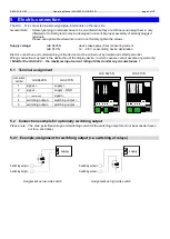
ONNECTION EXAMPLE FOR OPTIONALLY SWITCHING OUTPUT

 ................................................................................. 4


5.2.1


Example assignment for switching output (i.e. switching of relays) ............................................................ 4


6


CONFIGURATION ..................................................................................................................................................... 5


7


SELECTION OF SWITCHING AND ALARM POINTS ............................................................................................. 7


8


OFFSET AND SLOPE ADJUSTMENT ..................................................................................................................... 8


9


MIN-/MAX- VALUE MEMORY .................................................................................................................................. 8


10


ERROR CODES ........................................................................................................................................................ 9


11


SPECIFICATIONS ................................................................................................................................................... 10


Designated Use 

The GIA 0420 N and GIA 010 N are microprocessor controlled display devices.  

The different design types of the device have an input for:  
  - standard signal  4 

– 20 mA  (GIA 0420 N) 

  - standard signal  0 

– 10 V     (GIA 010 N) 

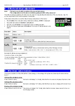
The measuring value is displayed on a 4-digit LCD display with max. display area ranging from -1999 to +9999 digits. 

The device additional features a switching output (NPN-output) which can be configured as 2-point controller or min-
/max alarm. The state of the output is displayed with an arrow at the LCD. 

The GIA 0420 … is designed for the connection of any measuring transducers (with a 4 to 20 mA output).  
This design type doesn't need an auxiliary supply as it is supplied by the measuring current. 

The GIA 

010 … is designed for the connection of any measuring transducers (with a 0 - 10 V output).  

The parameters and limit values can be input by buttons accessible at the rear side.  
The operating range of the display device can be directly adjusted to the transmitter without any additional accesso-
ries by simply entering the maximum and minimum measuring range limits as well as the decimal point position. 
All programmable parameters of the device are saved in an EEProm. In case of a current failure they will remain there 
for at least 10 years. 

The device is equipped with a self-diagnosis system continuously monitoring the essential parts of the device for their 
perfect functioning. Both the self-diagnosis and the measuring sensor monitoring for values exceeding or falling below 
permissible limits ensure maximum operational reliability of the device. 

Prior to delivery the device will be tested and completely calibrated.  

However, prior to you starting your operation make sure to configurate the device for your application.  
Please also refer to chapter "Configuration". 

2  General Note 

Read this document carefully and get used to the operation of the device before you use it. Keep this document within 
reach for consulting in case of doubt. 

Содержание Greisinger GIA 010 N

Страница 1: ...esstechnik GmbH Hans Sachs Str 26 93128 Regenstauf GERMANY Tel 49 9402 9383 0 info greisinger de www greisinger de Universal display for 4 20mA or 0 10V transmitter GIA 010 N as of version 1 0 Operating manual GIA 0420 N WEEE Reg Nr DE93889386 ...

Страница 2: ... 20 mA output This design type doesn t need an auxiliary supply as it is supplied by the measuring current The GIA 010 is designed for the connection of any measuring transducers with a 0 10 V output The parameters and limit values can be input by buttons accessible at the rear side The operating range of the display device can be directly adjusted to the transmitter without any additional accesso...

Страница 3: ...ble conditions for a longer time In case of doubt please return device to manufacturer for repair or maintenance 5 The buttons at the rear side are necessary for the configuration of the device The device is ESD sensitive at this area The configuration must be done considering adequate ESD safety measures 6 Warning Do not use these products as safety or emergency stop devices or in any other appli...

Страница 4: ...tion of the display device in which case we cannot assume any warranty Mind for the GIA 0420 the maximum input current rating of 40mA under any circumstances 5 1 Terminal assignment GIA 0420 N GIA 010 N connection number GIA 0420 N GIA 010 N 1 signal supply 2 signal supply GND 3 inexistent signal 4 switching output switching output 5 switching output switching output 5 2 Connection example for opt...

Страница 5: ...al 4mA D X Upper display range limit display high 1999 9999 This value is displayed for input signal 20mA L Measuring range limit OFF deactivated Exceeding of the measuring range limit is tolerable as long as value is within measuring range p r t note ON ER active display error The measuring range limit is exactly bounded by the input signal When exceeding or short falling the input signal the dev...

Страница 6: ...ng of the configuration menu 1 DEL only at outP 2P Delay of switching function of output 1 0 0 999 9 The set value is the time in seconds the device waits at least after switching off output 1 to switch it on again 1 ERR only at outP 2P Preferred position of output 1 ON OFF If an error occurs the device switches output 1 to active on or inactive off AL X only at outP AL F 1 Max alarm point AL LO D...

Страница 7: ...er Value Description Button 1 Button 2 and 3 1 ON only at outP 2P Switch on point of output 1 D LO D X Value at which output 1 should be switched on Value has to be between upper and lower measuring range limit set at the be ginning of the configuration menu 1 OFF only at outP 2P Switch off point of output 1 D LO D X Value at which output 1 should be switched off Value has to be between upper and ...

Страница 8: ...cale in The displayed value is calculated according to the following formula Display measured value offset di Lo 1 slope adjustment 100 di Lo Example for offset and slope adjustment Connection of pressure transmitter The device displays without offset and slope adjustment at 0 bar 0 08 at 20 bar 20 02 From this calculated offset 0 08 slope 20 02 0 08 19 94 difference 0 06 ideal slope actual slope ...

Страница 9: ...uration e g input signal Err 3 Display range has been exceeded Indicates that the valid display range 9999 digit of the device has been exceeded Possible causes Incorrect scale Remedies The error message will be reset if the display value is below 9999 Err 4 Values below display range Indicates that display value is below the valid display range of the device 1999 digit Possible causes Incorrect s...

Страница 10: ...Switching point hysteresis freely adjustable Switching voltage max 28 V Switching current max 50 mA Please note the switching output is not short circuits protected Reaction time 250 ms Nominal temperature 25 C Working conditions 20 50 C 0 80 non condensing Connection via 2 or 3 pin screw type plug in terminal max wire cross selection 1 5 mm Housing glass fibre reinforced noryl front panel PC 24 x...

Отзывы: