


E42.X.1X.6C-02
Operating Manual GIA 0420 N / GIA 010 N
page 8 of 10
8
Offset and slope adjustment
Note:
The device can be ESD sensitive at the area of the buttons.
The configuration must be done considering adequate ESD safety measures!
The offset and slope-adjustment function can be used for compensating the tolerance of the used sensor, resp. for
vernier adjustment of the used transducer / transmitter.
Follow these instructions to run the offset and slope adjustment of the device:
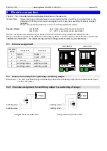
Press
button 3
for 2 seconds during actual value display, „
OFFS
“ is displayed.
Set parameter value with
button 2
and
button 3
.
Save the set with
button 1
, the parameter name is displayed again.
Proceed to the next parameter with
button 1
, the name of that parameter is dis-
played.
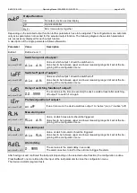
Parameter
Value
Description
Button 1
Button 2 and 3
OFFS
Offset
-5.00
…
5.00
The offset in digit
The set offset value is subtracted from measured value.
SCAL
Scale
-5.00
…
5.00
The scale in %.
The displayed value is calculated according to the following formula:
Display = (measured value - offset - di.Lo) * (1 + slope adjustment [% / 100] ) + di.Lo
Example for offset and slope adjustment:
Connection of pressure transmitter.
The device displays without offset and slope adjustment: at 0 bar = 0.08, at 20 bar = 20.02
From this calculated:
offset:
0.08
slope:
20.02
– 0.08 = 19.94
difference
:
0.06
(= ideal slope
– actual slope = 20.00 - 19.94)
Therefore this values should be set:
offset =
0.08
scale =
0.30
(= difference / actual slope = 0.06 / 19.94 = 0.0030 = 0.30% )
9
Min-/max- value memory
The device features a minimum/maximum-value storage. In this storage the highest and lowest performance data is
saved.
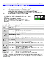
Calling of the minimum value:
Press button 3 shortly:
the device will display “Lo“ briefly, after that the min-value is displayed for about 2 sec.
Calling of the maximum value:
Press button 2 shortly:
the device will display “Hi“ briefly, after that the max-value is displayed for about 2 sec.
Erasing of the min/max values:
Press button 2 and 3 for 2 sec.:
The device will display “CLr“ briefly, after that the min/max-values are set to the cur-
rent displayed value.
T1
T3
T2
5 4
2 1
3


