background image


20 


Radio receiver X7 

Pull switch X7 

Intermediate open X8 

Radio receiver X7 

Pull switch X7 

Intermediate open X8 


1 2 3 4

24V

X7

A13


A14

4

3

X7

S19

A15

1 2

4

3

S17

X8


Red/green traffic lights X20 / X21 

Magnetic brake X20 / X21 

Red/green traffic lights X20 / X21 

Magnetic brake X20 / X21 

20

.1

20

.2

20

.3

H1

1.

9

1.

8

21

.1

21

.2

21

.3

X20/

H2


20

.1

20

.2

20

.3

1.

9

1.

8

21

.1

21

.2

21

.3

X20/

Y1

G1

C1


H1  Traffic light, green 

G1  Rectifier 

H2  Traffic light, red 

Y1  Magnetic brake 


Содержание TS 971

Страница 1: ...Installation instructions Door control TS 971 Automatic control panel with radio Version 51171521 en Version i 04 2019 0000000 0000 51171521 XXXXX ...

Страница 2: ...2 GfA ELEKTROMATEN GmbH Co KG Wiesenstraße 81 40549 Düsseldorf www gfa elektromaten de info gfa elektromaten de ...

Страница 3: ...pid adjustment of final limit positions 15 NES Rapid adjustment of final limit positions 16 6 Advanced electrical installation 17 Connection of spiral cable Light curtain X2 17 Door safety switch Crash switch X2 18 External supply X1 18 Emergency stop X3 18 Automatic closing On Off X4 18 External Control device X5 19 Photo cell X6 19 Light curtain X6 19 Radio receiver X7 20 Pull switch X7 20 Inter...

Страница 4: ...door safety switch function 37 X2 Input for safety devices 39 Installation of the spiral cable 40 Integrated WSD door module 43 EMERGENCY operation 45 X3 Input emergency stop 45 10 Functional description 46 X 24 VDC voltage supply 46 X1 Mains supply of the control and supply of external devices 46 X4 Input automatic closing Off On 47 X5 Input control device 47 X6 Input Through reflective photo cel...

Страница 5: ...y device 58 Standby function 58 Illumination of the built in push button of the door control 58 11 Status display 59 Faults 59 Commands 64 Status indications 65 12 Explanation of symbols 66 13 Declaration of incorporation Declaration of conformity 68 Symbols Warning Risk of injury or danger to life Warning Danger to life from electrical current Note Important information Prompt Required action Ill...

Страница 6: ...structions may result in severe injury or death Please read these instructions before using the product Keep these instructions handy Please include these instructions when you pass on the product Installation and commissioning are to be performed by skilled personnel only Only trained electrical craftsmen are permitted to work on electrical equipment They must assess the tasks assigned to them re...

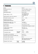
Страница 7: ...mains supply X1 L X1 N Protection via F1 micro fuse 1 N 230 V 1 6 A time lag Control inputs 24 V DC type 10 mA Relay contacts 2 potential free changeover contacts Loading of relay contacts ohmic inductive 230 V AC 1 A 24 V DC 0 4 A Control power consumption 18 W Temperature range Operation Storage 10 C 50 C 0 C 50 C Air humidity non condensing up to 93 Protection class of housing with CEE plug IP ...

Страница 8: ...ound that is free of vibration Only vertical mounting position allowed Door must be in clear view from place of installation Requirements The permissible loads on walls mountings connection and transmission elements must not be exceeded Mounting The control is mounted via 4 elongated holes ...

Страница 9: ...site backup fuse and mains disconnector Only use all current sensitive earth leakage circuit breakers type B for FI drive units Connection to the indoor installation via an all pole disconnector unit with current 10 A as per EN 12453 e g CEE plug connector main switch Note Connect this door control only to drive units that have a digital limit switch DES with proof of performance level c PLc Obser...

Страница 10: ...2 V Phase V 7 gn Ground 1 U Phase U 8 ye Channel A RS485 4 N Neutral conductor N 9 gy Safety circuit PE PE 10 pk 8 V DC supply voltage Ⓐ NES Ⓔ X12 NES Pin Core Term Description 5 wh 11 Limit switch common 24 V wire link to 7 9 5 14 6 bn 12 S5 Auxiliary limit switch 7 gn 6 S3 Open limit switch 8 ye 15 S6 Auxiliary limit switch 9 gy 8 S4 CLOSE limit switch 10 pk 4 Safety circuit ...

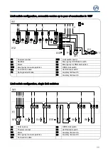
Страница 11: ... limit switch S10 Emergency manual operation S3 OPEN limit switch W1 Connection cable S4 CLOSE limit switch Y1 Spring loaded brake S5 Auxiliary limit switch S6 Auxiliary limit switch Limit switch configuration single limit switches 5 6 7 10 9 3 2 1 4PE M1 S10 F1 S4 S3 S5 S6 W1 A1 A1 Terminal box S3 OPEN limit switch F1 Thermal contact S4 CLOSE limit switch M1 Motor S5 Auxiliary limit switch S10 Em...

Страница 12: ...trical installation Remove covers Open cable entry or Insert and connect connection cable in the open cable entry from below or from above Properly tighten cable glands Avoid damage to parts Open cable entry with suitable tool ...

Страница 13: ...60 Hz 1 N PE asym 220 230 V 50 60 Hz L1 L2 L3 N PE L1 L2 L3 PE N PE SI 25 15 WS SI 45 7 WS N PE SI 25 15 WS SI 45 7 WS Mains supply to control 3 Completing the electrical installation Install and tighten cable entries and or cable glands For commissioning of the control leave the covers open ...

Страница 14: ...time lag X2 Safety edge and door safety switch MOT Motor socket S Selector switch X3 Emergency STOP control device S11 OPEN push button X4 Automatic closing On Off S12 STOP push button X5 Control device external three push button S13 CLOSE push button X6 Through reflective photo cell T Internal aerial 434 MHz X7 Pull switch external radio receiver UBS Universal command sensor socket X8 Intermediat...

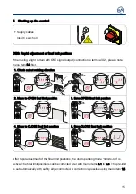
Страница 15: ...ting direction 2 Move to OPEN final limit position 3 Save OPEN final limit position 4 Move to CLOSE final limit position 5 Save CLOSE final limit position After rapid adjustment of the final limit positions the door operating mode hold to run is active The final limit positions can be corrected later with menu items 1 1 to 1 4 The pre limit is set automatically with safety edge connected A correct...

Страница 16: ...it positions When using a light curtain with OSE signal output connection to terminal X2 please note menu item 0 3 first 1 Check output rotating direction 2 Move to OPEN final limit position and adjust S3 OPEN limit switch 3 Move to CLOSE final limit position 5cm above the ground and adjust S5 pre limit switch 4 Move to CLOSE final limit position and adjust S4 CLOSE limit switch ...

Страница 17: ... SK1 SK2 A18 DW 1K2 R2 A18 Junction box ST Mains supply ST Input for door safety switch SK1 Input pneumatic safety edge SK2 DW Pneumatic switch R2 End of line resistor 1k2 X2 Door control socket Optical safety edge system 2 3 4 2 1 2 3 2 5 2 2 2 4 X2 1 2 3 4 ST ST SK b SK g SK w A19 br gn w B3 B2 A19 Junction box ST Mains supply ST Input for door safety switch SK b Mains supply brown SK g Output g...

Страница 18: ...n box switch S30 Pass door switch NC contact S38 Crash switch NC contact S39 Crash switch NO contact S31 Slack rope switch NC contact External supply X1 Emergency stop X3 Automatic closing On Off X4 External supply X1 Emergency stop X3 Automatic closing On Off X4 F1 1 6At F1 A1 X3 A2 2 1 S15 X4 A3 1 2 4 3 S17 A1 External device A2 Control device A3 Control device F1 Micro fuse 1 6 A Emergency stop...

Страница 19: ...11 1 2 3 24V A12 PNP A8 Reflective photo cell Through beam photo cell Through beam photo cell A9 Transmitter A11 Transmitter A10 Receiver A12 Receiver Light curtain X6 Light curtain X6 X21 21 1 21 2 21 3 24V 24V X20 20 1 20 2 20 3 24V 24V X6 1 2 24V A25 1 2 3 4 5 24V A26 24V 24V PNP X6 1 2 24V A27 1 2 3 24V A28 24V 24V X20 Function relay Light curtain Light curtain X21 Function relay A25 Transmitt...

Страница 20: ...7 A13 A14 4 3 X7 S19 A15 1 2 4 3 S17 X8 Red green traffic lights X20 X21 Magnetic brake X20 X21 Red green traffic lights X20 X21 Magnetic brake X20 X21 20 1 20 2 20 3 H1 1 9 1 8 21 1 21 2 21 3 X20 H2 20 1 20 2 20 3 1 9 1 8 21 1 21 2 21 3 X20 Y1 G1 C1 H1 Traffic light green G1 Rectifier H2 Traffic light red Y1 Magnetic brake ...

Страница 21: ...for system 2 Optical upper changeover position IR G1 Lithium battery 9000 mAh Electrical lower changeover position X1 2 Connection point for door safety switch KL1 Terminal for ST3 Socket for optical sensor System 2 connection cable Electrical safety edge ST1 Socket for optical sensor Electrical safety edge 8k2 to WSD door module Electrical safety edge 8k2 to WSD door module Optical safety edge OS...

Страница 22: ...oor module Optical safety edge OSE System 2 to WSD door module A23 WSD door module A24 System 2 end box A24 Door safety switch on WSD door module Door safety switch on WSD door module 2 1 S38 A24 System 2 end box A21 2 1 S38 A21 2 1 S38 A24 X1 X2 ...

Страница 23: ...or example Available channels Teach in WSD door module connected dot on right is lit Note Use of a safety edge only possible via menu item 0 1 door operating mode 3 4 or 6 Completing the advanced electrical installation If required connect other electrical equipment and or safety devices Install and tighten cable entries and or cable glands ...

Страница 24: ...amming 1 Start programming 2 Select menu item and confirm 3 a Set and store functions 3 b Set and store positions DES 4 Exit programming Note Complete programming is only possible after setting the final limit positions ...

Страница 25: ...ce Hold to run OPEN Hold to run CLOSE with active safety edge Output rotating direction Maintain output rotating direction Change output rotating direction Special function Spiral cable or WSD Light curtain Parallel operation of light curtain and WSD NOTE This menu item is only enabled at initial operation or after a complete reset The selection must be made before setting the final limit position...

Страница 26: ...ion CLOSE correction Fine correction pre limit switch for safety edge DES Without door movement OPEN correction CLOSE correction Adjust intermediate open X8 DES Approach and store desired door position Setting for position of relay 1 switching point DES Select relay function via menu item 2 7 Approach and store desired door position Setting for position of relay 2 switching point DES Select relay ...

Страница 27: ...ure maximum distance between the door controls with the same channels Note taught in channels in the controls housing Important for service work Pay attention to the WSD door module manual Safety edge function in the pre limit area Safety edge active Safety edge inactive Ground adjustment DES Activation of safety edge at ground contact Reversing in overrun area DES Overrun correction DES Off On Do...

Страница 28: ...utomatic closing and CLOSE command when actuated for 1 5 seconds Reverse in case of obstacle Off recommended for light curtains Adjustable from 1 to 10 Number of safety device actuations Pull switch or radio receiver function X7 Type of impuls 1 Door is in OPEN final limit position CLOSE command Door is not at OPEN final limit position OPEN command Type of impuls 2 Command sequence OPEN STOP CLOSE...

Страница 29: ...seconds CLOSE final limit position Permanently lit for 3 seconds Red lamp permanently lit during door movement OPEN final limit position Permanently lit for 3 seconds CLOSE final limit position Off Dock leveller release or permanent green light Active only in OPEN final limit position Permanent contact in CLOSE final limit position Light sensing device 1 second pulse at each OPEN command Permanent...

Страница 30: ...30 Door functions Part 4 Intermediate open function All command inputs Input X7 2 and internal radio receiver Input X5 3 and OPEN push button of control ...

Страница 31: ...tact After activation Hold to run door operating mode Crash switch as NO contact After activation Hold to run door operating mode Crash switch as NC contact After activation Reversing in OPEN final limit position Reset after contact reset otherwise Hold to run door operating mode Crash switch as NO contact After activation Reversing in OPEN final limit position Reset after contact reset otherwise ...

Страница 32: ...duced speed Output speed in rpm 0 Off Changeover position to CLOSE output speed with adherence to minimum opening height requirement of 2 5 m Approach and store desired door position OPEN acceleration DI Steps of 1 0 seconds FI Steps of 0 1 seconds CLOSE acceleration DI Steps of 1 0 seconds FI Steps of 0 1 seconds OPEN deceleration DI Steps of 1 0 seconds FI Steps of 0 1 seconds CLOSE deceleration...

Страница 33: ...4 MHz Internal radio receiver deactivated Fixcode GfA Tedsen Teleco COD1 Rolling code of various providers GfA UK JCM Dickert Fixed code RDA Radio receiver function Teach in of a handheld transmitter Cancellation of a taught in handheld transmitter Cancellation of all taught in handheld transmitter ...

Страница 34: ... item 8 5 Changeover to Hold to run door operating mode Status indication CS appears in turns with value set by menu item 8 5 Changeover to Hold to run door operating mode Status indication CS appears in turns with value set by menu item 8 5 Option Press STOP button for 3 seconds to deactivate changeover and status indications for 500 cycles Status indication CS appears in turns with value set by ...

Страница 35: ... of ten consecutively M HT 1 000 000 100 000 ZT T 10 000 1 000 H Z 100 10 E 1 Cycle counter of the last change in programming Number of activations of slack rope pass door and crash switch Software version The software version of the control is displayed For direct inverter or frequency inverter drive units the software version of the motor is displayed as well Deleting readout Deleting readout De...

Страница 36: ...t in WSD door module Displaying of missing data is done by Data indicated alternately 1 Version of master radio module 2 Type of safety edge 0 0 none 0 1 1k2 0 2 8k2 0 3 optic 3 Door safety switch 0 0 inactive 0 1 active 4 Battery voltage 5 Assigned selected communication channel 6 Signal quality ranging from 0 99 ...

Страница 37: ...erter Hold to run door operating mode at crawling speed only Fault reset only possible in OPEN final limit position Press the STOP button of the door control for 3 seconds 3 Crash switch as NO contact Like function 2 4 Crash switch as NC contact with reversing Door stops reversing Fault reset only possible in OPEN final limit position Takes place automatically as soon as the switching contact has ...

Страница 38: ...The F1 7 fault indication appears if there is a failure Crash switch as NC or NO contact The crash switch is activated if the door is pushed out of the mechanical guideance If the switching contact is activated the door is stopped fault indication F4 5 is displayed and a changeover to Hold to run door operating mode is carried out Movement of the door is only possible via the built in push button ...

Страница 39: ...e wave switch system NC with a terminal resistance of 1k2 5 and 0 25 W Upon activation or permanent disconnection of the current circuit the F2 6 fault indication appears If there is a short circuit fault indication F2 7 is displayed The pressure wave switch system needs to be tested with CLOSE final limit position The test phase is initiated automatically by the pre limit for DES If no switching ...

Страница 40: ...The safety edge system is connected via the 3 pole plug and the slack rope or the pass door via the 2 pole plug Important Check position of S5 pre limit switch on the safety edge only for NES When the door is opened 5cm a reversing must be executed if the safety edge has been activated Function Safety edge function in the pre limit area Menu item 2 1 Function Reaction to activation of safety edge ...

Страница 41: ...Note Reversing upwards in the overrun area To maintain the operating forces in the pre limit area At high speeds With DES limit switch only Function for FI drive units not necessary Function Overrun correction function only DES Menu item 2 2 Automatic limit switch correction to achieve a constant CLOSE position Function Overrun correction 0 Off 1 On Note Overrun correction With DES limit switch on...

Страница 42: ...ess safety device is triggered the door stops the closing attempt and then moves back to its starting position With menu item 2 5 reversing in case of obstacle you can set the number of closing attempts For example if the factory setting is 2 the door will try to close twice and then stop in the upper start position if there is an obstacle Fault indication F2 2 then appears in the menu Note To res...

Страница 43: ...age to components Use additional splash guard 40017478 in car washes to avoid cracked seals For example plasticizer surfactants Keep imported cables as short as possible to plug connections and terminals Avoid installing the lines directly above the receiver board Avoid bending the aerial Carefully close the cover Usable safety devices Safety edge systems 8k2 resistor evaluation Optical safety edg...

Страница 44: ...n Door movement only possible via EMERGENCY operation When performing annual maintenance tasks involving the door system replace the WSD door module battery as a precautionary measure Menu item 9 6 Alternating display of WSD door module statuses including Version of master radio module Type of safety edge 0 0 none 0 1 1k2 0 2 8k2 0 3 optic Door safety switch 0 0 inactive 0 1 active Battery voltage...

Страница 45: ...ote The door cannot be moved in case of F1 3 and F1 4 fault indications for reasons of operating safety Activation of EMERGENCY operation Use the built in push button of the control to press and hold the STOP button while simultaneously pressing the OPEN or CLOSE push button to move the door X3 Input emergency stop Connection of an emergency stop control device as per EN 13850 or an evaluation uni...

Страница 46: ...rminals X1 1 1 to X1 1 4 and PE Various mains supplies 3 N 3 1 N for symmetric and asymmetric motors Note Pay attention to the Mains supply and Mains supply connection to control descriptions Supply of external devices Connection of external devices for 230 V such as photo cell radio receiver relay etc via terminals X1 1 8 and X1 1 9 Note The mains supply of external devices using terminals X1 1 8...

Страница 47: ...ce Warning Hold to run door operating mode The door must be fully visible from the operating point The door operating mode 3 allows a place of installation of the control device without sight of the door Note Application without STOP push button Connect wire link X5 1 to wire link X5 2 If the safety edge or photo cell fails the control device will not function ...

Страница 48: ...tion without safety edge Connect resistor 8k2 via the terminals X2 3 and X2 4 Photo cells must not be used via the UBS system if a light curtain is used Do not use menu item 3 2 for the light curtain To test the light curtain activate relay contact X20 or X21 The relay functions are described under menu item 2 7 2 8 If the light beam is interrupted fault indication F4 6 appears With every CLOSE co...

Страница 49: ...ds after the interruption period for the light beam has ended Reaction of automatic closing to photo cell light curtain Menu item 2 4 Function Reaction of automatic closing to photo cell light curtain 0 No action 1 Stopping automatic closing The door closes 3 seconds after the interruption period for the light beam has ended 2 Vessel recognition The door closes after the interruption period for th...

Страница 50: ...The light beam must be interrupted twice at the same door position The teach in mode is then terminated The photo cell has no function below this stored door position Teach in mode display Upon exiting the programming When the light beam is interrupted for the first time After the second interruption to the light beam at the same door position and with the CLOSE final limit position reached Note I...

Страница 51: ...t be potential free NO contact Pull switch or radio receiver function Menu item 2 6 Type of impuls Reaction upon activation 1 Door is in OPEN final limit position resp intermediate open position The door CLOSES From all other door positions or door movements The door OPENS 2 OPEN STOP CLOSE STOP OPEN command order 3 Door always executes OPEN movement ...

Страница 52: ... deleted via menu item 7 7 Note A combination of different radio transmitter manufacturers is possible Only use 434 MHz handheld transmitters Up to 64 radio channels can be taught Teach in of radio transmitter Teach in of handheld transmitters 1 Select radio transmitter manufacturer s system 2 Activate radio transmitter 3 Carry out teaching in 4 Switch to door operation ...

Страница 53: ...ansmitter Deleting an individual radio transmitter 1 Activate delete 10 seconds active 2 Delete 3 Switch to door operation Deleting all radio transmitters Deleting all radio transmitters 1 Delete all channels 2 Switch to door operation ...

Страница 54: ...can move back to the OPEN final limit position Intermediate open function Menu item 2 9 Function Intermediate open 1 All command inputs 2 Intermediate open via X7 pull switch and internal radio receiver OPEN final limit position via all other control devices 3 Intermediate open via external control devices X5 and OPEN push button of the control OPEN final limit position via all other control devic...

Страница 55: ...u item 3 1 The force monitoring can only be used with fully balanced doors and drive units with DES It should be able to detect when persons are moving with the door Warning The force monitoring is no substitute for safety measures in providing protection against the trapping hazard Function Force monitoring 0 Off 2 1 0 2 Low limit value 1 0 High limit value Important Force monitoring for doors wi...

Страница 56: ...ly the Hold to run door operating mode is possible and the F4 1 fault indication is displayed The resetting occurs when a final limit position for the door is reached Travel time monitoring NES only Menu item 3 3 The set travel time is automatically compared with the time measured for movement between the final limit positions If the travel time is exceeded the F5 6 fault indication appears Fault ...

Страница 57: ...ed automatically Note The UBS devices function in the same way as wired control devices UBS connection UBS connection Three push button Reflective photo cell External Radio receiver Reversing duration adjustment Menu item 3 8 Shortening the reversing duration serves for a reduction of the operating forces Extending it on the other hand will reduce the wear on the door mechanism ...

Страница 58: ...isplay for active WSD door module wireles safety device If the WSD door module wireless safety device is active an additional red point is displayed on the right hand digit display Standby function If there is no fault or command pending the control switches to Standby If the automatic closing duration is longer than 60 seconds the control also switches to Standby Only the left dot is lit up With ...

Страница 59: ...ate measures Terminals X3 1 X3 2 are open Emergency stop has been activated Check emergency stop Check whether the connection cable is connected Radio transmission of WSD door module is faulty Radio channel assigned twice Use menu item 9 6 to read off the radio channel Use menu item 2 0 to manually assign the radio channels Moisture in WSD door module Replace WSD door module und use a splash guard...

Страница 60: ...n cable Replace photo cell if necessary Maximum number of reversing movements for door through safety edge system activation has been reached Only with automatic closing Obstacles along the door travel path Check whether the safety edge system is correctly functioning Activation of safety edge 8k2 Check whether the safety edge system is correctly functioning Check whether the connection cable has ...

Страница 61: ...ncy manual operation Reset of control via menu item 9 5 Check door and door drive unit for stalling Warning Danger of the door dropping Stalling may indicate the anti fall back device if incorporated has activated Take appropriate measures DES CLOSE emergency stop switch reached In the voltage free state move the door back via emergency manual operation NES Faulty activation of the S5 pre limit sw...

Страница 62: ...ntroller Switch control off and on Replace control if necessary ROM error Switch control off and on Replace control if necessary CPU error Switch control off and on Replace control if necessary RAM error Switch control off and on Replace control if necessary Internal fault of control Switch control off and on Replace control if necessary Fault of digital limit switch DES Check DES connector and co...

Страница 63: ...n the DC voltage sink Execute fault clearance trough movement command Check mains input voltage Change slope durations speeds Excess voltage in the DC voltage link Check mains input voltage Execute fault clearance trough movement command Change slope durations speeds Temperature limit exceeded Check for overload of the drive unit Cool down the drive unit and reduce the number of cycles Permanent c...

Страница 64: ...A CLOSE command is present Inputs X5 4 X7 2 internal radio system UBS control device or UBS radio receiver Status indications Status display Description Preset value for maintenance cycle counter reached Dot on left is not lit control circuit has a short circuit or is overloaded Dot on right is lit internal WSD door module is active Function for changing the rotating direction is activated only po...

Страница 65: ...ve Stop between the set final limit positions Stop at the OPEN final limit position Stop at the intermediate stop position Stop at the CLOSE final limit position Teaching in or deleting of the WSD door module or handheld transmitter is confirmed Blocking of programming option confirmed Flashing display Unblocking of programming option active Interruption of the photo cell function At first interru...

Страница 66: ...nu value on the right Factory setting of the minimum limit dependent on drive unit Factory setting of the maximum limit dependent on drive unit Setting range Prompt Select menu item or value turn selector switch S to the left or to the right Prompt View menu item press selector switch S once Prompt Store press selector switch S once Prompt Start programming actuate the selector switch S for three ...

Страница 67: ...button Prompt Save press stop button once via built in push button Prompt Save press stop button for three seconds via built in push button Prompt Reset the control press stop button for three seconds via built in push button Prompt Move to door position Prompt Move to door position for OPEN final limit position Prompt Move to pre limit Prompt Move to door position for CLOSE final limit position ...

Страница 68: ...l documents is the undersigned Düsseldorf 10 08 2018 Stephan Kleine CEO Signature The following requirements from Appendix I of the Machinery Directive 2006 42 EC are met 1 1 2 1 1 3 1 1 5 1 2 1 1 2 2 1 2 3 1 2 4 2 1 2 5 1 2 6 1 3 1 1 3 2 1 3 3 1 3 4 1 3 9 1 5 1 1 5 2 1 5 4 1 5 5 1 5 6 1 5 7 1 5 8 1 5 9 1 5 10 1 5 11 1 5 13 1 6 1 1 6 2 1 6 4 1 7 1 1 1 7 1 2 1 7 2 1 7 3 1 7 4 3 Standards applied EN...

Отзывы: