25
25
4.6.1.2 Configuring PLC Functions
In order to configure the PLC (GPIO) functions,
let’s start the
GP-series
operation at first. Open
the Coyote Application and click “Configure”. The
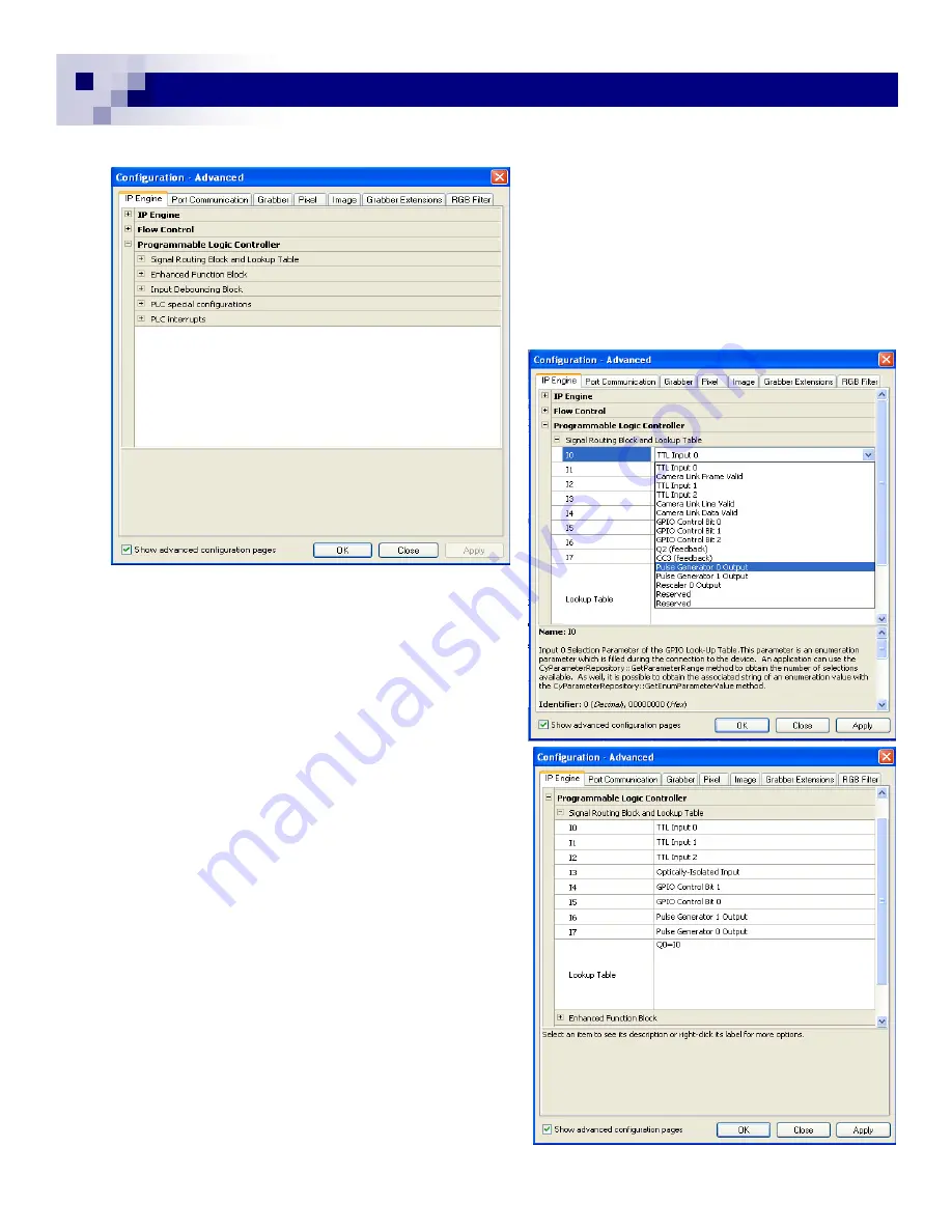
PLC configuration is in the “IP Engine” tab. With
the advanced configuration marked, there are 5
segments of PLC configuration blocks. (Fig. 38)
In this manual, we will go through Signal Routing
Block, Lookup Table (LUT), and Enhanced
Function
Block”.
4.6.1.3 Signal Routing Block
This defines the input node to each input signal from
I0 to I3. The I0 is External Trigger Input for the cam-
era (default). If the internal software trigger is re-
quired, you can choose Pulse Generator 0 output or
GPIO Control Bit 0 for the I0. The selection of these
functions is shown in Fig. 39. For Opto-isolated in-
puts, this section is also TTL level after signal con-
version in previous blocks. For the practice, let’s se-
lect “Pulse Generator 0” and click “Apply”.
4.6.1.4 LUT
The Lookup Table connects each Input and Output in-
cluding programming of the functionalities. In this sec-
tion, we are using simple connections between IOs.
To connect I0 to the specific output of TTL_OUT 0 for
the trigger function, type ”Q0=I0” in LUT section. In
Fig. 40, I0 is TTL Input 0 and Q0=I0. This allows the
External Trigger to go through PLC, and output the
Internal Trigger directly to the camera module.
You now choose “Pulse Generator 0” and the Internal
Trigger is now connected to the Pulse Generator 0.
Click “apply”.
To see the changes of camera behavior, you have to
go to the “Port Communication” tab and change the
mode to Async.
Let’s select the Pulse-width Control. Type “57 00 23
00 00 00 02” <send>. Without the external trigger or
the internal software trigger, the image may freeze
and wait for the trigger.
GEViCAM Inc
Fig. 38
Fig. 39
Fig. 40
Содержание GP-151400
Страница 39: ...39 39 GEViCAM Inc MEMO ...


