June 15, 2011
9
2. To enable external control of Beeper or LED, select Beeper, Green LED or Red LED.
Beeper: Enables the external control of Beeper.
Green LED: Changes the standby color from blue to green.
Red LED: Changes the standby color from blue to red.
3. Select Slave from the Master / Slave drop-down list and select an ID number for the
reader. The ID number is ranging from 0 to 7.
4. Click Setup GO. The settings are sent to GV-R1352.
After the above settings, you need to connect the Beeper, Red LED and Green LED wires
from GV-R1352 to GV-AS Controller.
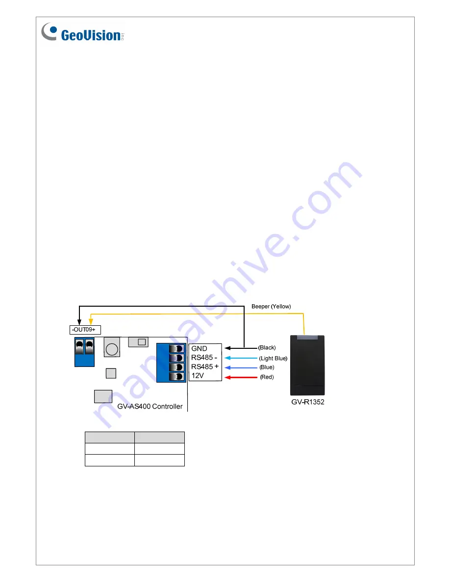
6.2 Wiring the Beeper and LED to GV-AS Controller
To wire the beeper and LED to GV-AS Controller, follow these steps. We will use GV-AS400
Controller as an example. Connect the control wires of GV-R1352’s Beeper, Red LED or
Green LED to any of outputs 9 ~ 16 on GV-AS400 Controller. The following diagram is an
example on connecting the beeper wire of GV-R1352 to GV-AS400 Controller.
Wire Color Function
Black
GND
Yellow
Beeper


