SY-SIX-CTRL-DIN-1D | Synergis IX DIN Rail Single Door Controller | Installation Manual
Last Updated August 2018
20
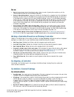
Parity Options (1-4)
There can be up to 4 blocks of parity calculated over the received data.
Parity Type
: The parity type defines the method of calculating the parity for the block. This is either Even
or Odd Parity.
Parity Location
: The parity location defines where the location of the parity bit in the received data.
Parity Start
: Defines where the location of the parity block starts in the received data.
Parity End
: Defines where the location of the parity block ends in the received data.
Bit Options (1-4)
Set Bit
: A set bit defines a location in the received data that must always be set (or a logical '1'). The set
bit defines where the location of the bit in the received data.
Clear Bit
: A clear bit defines a location in the received data that must always be cleared (or a logical '0').
The clear bit defines the location of the bit in the received data.
Addressing Modules
Traditionally the network address of a module has been set using a bank of DIP Switches located on each
individual module. The Synergis system modules enable addresses to be configured electronically via the
Synergis software.
The factory default address of all DIN Rail mount modules is 254. If this address is not changed, the module
will not be able to register with the Controller.
To change the network address of a module:
1. Ensure the Controller is correctly powered and is communicating with the Synergis software. Refer to
Synergis software documentation for more information about the software configuration.
2. Connect the module(s) that require addressing to the module network. Make sure that the Power light on
each module is on and that the Status light begins flashing rapidly.
3. Allow some time for the module(s) to attempt to register with the Controller.
If the module has the default address of 254 or has the same address as another module, the
Fault
light will begin flashing at 1 second intervals.
If the module has been previously addressed and is not a duplicate then it will succeed in registering
and the
Status
light will begin flashing at 1 second intervals.
4. Once all modules have completed the registration process (successful or not), open the Auto-addressing
window in the software by right clicking on the Controller and selecting
Module Addressing
.
5. If the address can be changed electronically this is indicated in the
Address can be changed
column and
the selector in the
Address
column is enabled. The
Update
and
Find
options will also be enabled. If it is
not clear which module is which, click
Find
to instruct the respective module to flash its Status light for the
specified period of time. Modules can also be identified by comparing the serial number on the label with
that shown in the software. Ensure that you are clear which module is which before assigning addresses
to them.
6. Enter an address for the relevant module(s) by selecting an option from the
Address
column. When an
address has been selected but has not yet been updated on the module, it is shown in red. Modules can
be updated individually by clicking the option in the
Update
column, or all at once using the
Update All
button. Allow about 5 seconds per module for the new address to be sent and registered.


