Copyright of the European Union is effective (Copyright EU) (c) 2016 GENEREX GmbH, Hamburg, Germany, All rights reserved
TEL +49(40)22692910 - EMAIL [email protected] - WEB www.generex.de (This and all other product datasheets are available for download.)
17
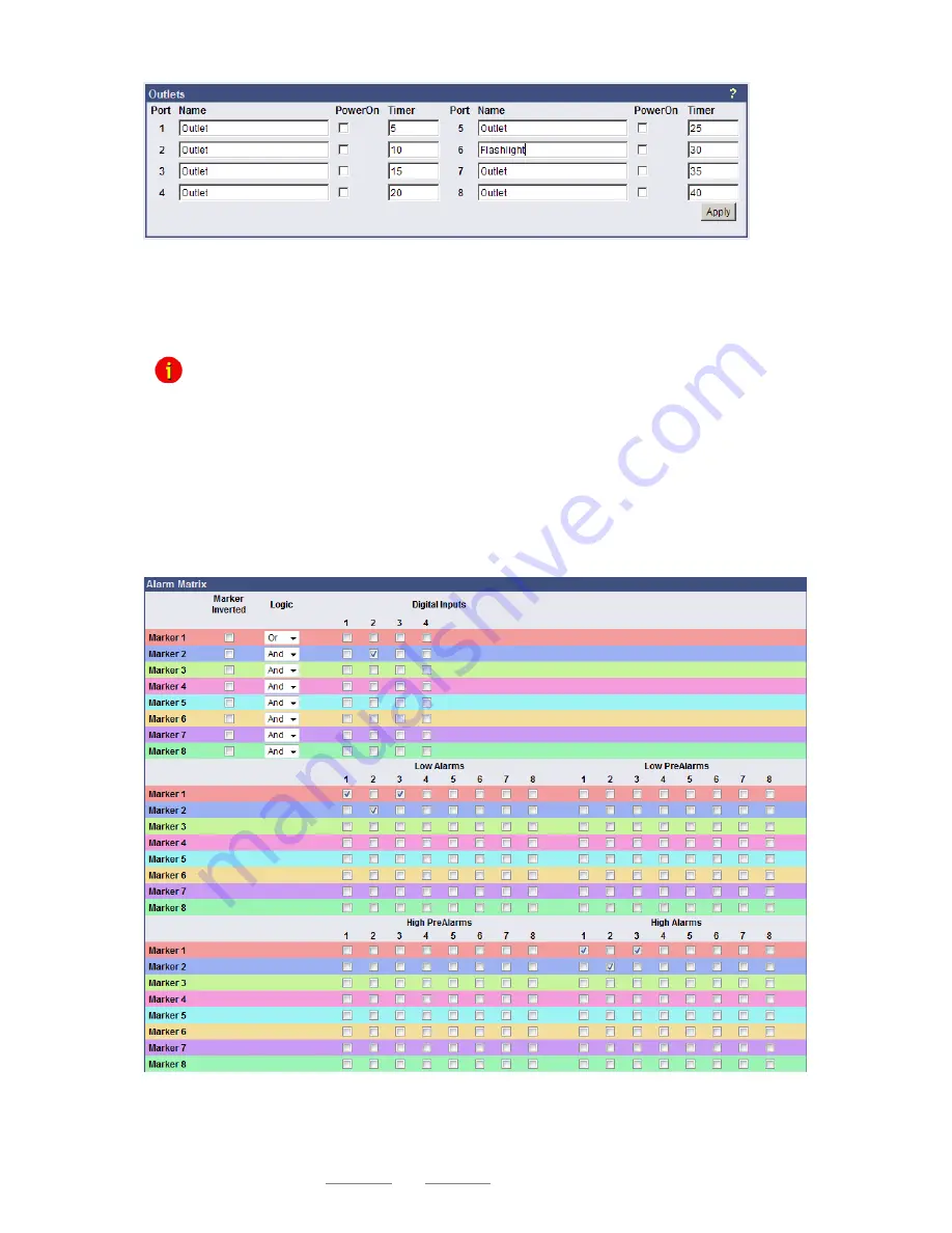
Figure 22:
HTTP configuration - Outlets
Furthermore it is possible to attach a timer value to each Outlet. This determinates how long an outlet
will be switched (in seconds). Set the timer value to
“0” if the outlet is to be switched without any time
limit (application example: To switch on a buzzer for a specific timeframe).
Note: If you do not want to use a name for the Analog-, Digital Inputs or rather the Outlets,
please set the following into the single name area:
4.2
Alarm matrix
The following
“Alarm Matrix” gives you numerous possibilities to configure dependencies between
different alarm states and to join them to different outlets. This makes it possible to process an alarm
scenario in dependency of the state of several input sensors. (For example: An alarm scenario is to be
released only if two temperature sensors are out of range or if the air condition is not active.)
Figure 23:
Alarm matrix
– Marker configuration
In the figure above is shown the alarm matrix with its 8 markers to be set or unset. Each marker
thereby is a new state on which specific alarm scenarios can be released.


