


5
2.1.2 REMOTE
CONNECTION
To connect remotely via modem, the PM-SC must have been con-
nected to a telephone jack and the phone number must be known.
Simply start GenLink (see the New Generation GenLink manual)
and set the connection type to “modem link.” Edit the “User site
table” and create a new entry for the PM-SC. This is done by sim-
ply clicking on one of the fields shown in the table and entering the
data. There is one row per entry and to create a new entry, click on
an empty row. To edit an entry, simply click on the cell to be edited.
The phone number for the PM-SC is the only value that must be
entered (its Modbus address is set by default to 100 but can be
changed via GenLink). All other fields are optional.
Once the data has been edited, click on “Apply” to save the
changes. Select the desired row from the table by clicking on the
gray cell to the left of the row and then click “Connect”.
2.1.3 LAN/INTERNET
CONNECTION
To connect via the Internet or via a local area network (Ethernet
LAN) a special converter box is required between the PM-SC’s
RS232 connector and the LAN. This can be obtained by contacting
the manufacturer's service department. The converter box needs
to be assigned either a network address, for connection from a PC
connected to the LAN, or an internet address for remote access.
In either case the manufacturer recommends the box is installed
with the aid of a competent IT professional. The “Device installer”
program (supplied) is used to assign the address and set up the
RS232 port on the converter. Run the device installer and use
the "search “ button to find the device on your network. Click on
the device to bring up extra menu’s in device installer. Click on
“Configure” and then select “Ports” to set up the device’s RS232
port. Set the baud rate to match the port in the PM-SC. We suggest
the following settings for optimal use:
57600 baud
•
8 data bits
•
no parity
•
one stop bit
•
no hand shaking
•
You must ensure this is how you have set the Genlink port (port
2) on the PM-SC . Note if you need to change the baud rate in the
PM-SC you must power the panel off and back on again for it to
take effect. In an MPS configuration you should use the 57600
baud setting for all communications with the generators (port 0).
Special port re-direction software will need to be installed on the
PC as well as Genlink, this is supplied with the converter box.
Use the re-direction software to select an unused port on your PC
that will be re-directed to the PC’s LAN connection, for example
com port 8. To select this port, use the “com setup” button and
click on the port number you want to use. Assign that port to the
address you have given your converter box via the “Add IP” but-
ton. Enter the address into the “Host” field, and enter 3001 into
the port field.
When Genlink is started, select the new com port via the tools
menu as described above. This will then always default to the LAN
as the method of connection.
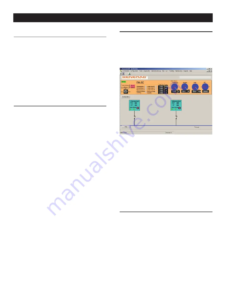
3.1 PROGRAMMING THE PM-SC
After connecting, the screen in Figure 3.1 will be displayed. If
you have any problems connecting such as the wrong Modbus
address, Genlink has tools to allow you to troubleshoot the con-
nection (see “Connection Problems”).
Figure 3.1
This screen is the mimic of the whole system, showing the com-
mon generator bus connections, the generators and their internal
bus contactors. The live portions of the circuit will be shown in
red. The positions of the contactors are actual and will change as
the generators start. Scrolling around the screen is accomplished
using the slider bars. The section with the black background at the
top of the screen refers to the total values on the common genera-
tor bus, and the cyan blocks at the bottom of the screen refer to the
individual generators. The blue “utility option” meters section will
only display utility power etc if utility CT’s have been purchased.
To look at a generator’s parameters (i.e to “drill down” to a genera-
tor), click on the generator in question. It is then possible to exam-
ine the generator’s parameters and change them in the normal way
(see New Generation GenLink manual). A report of the generator’s
status and settings can be printed.
3.1.1 GENERATOR
SETTINGS
To program the PM-SC system itself, click on the “Configuration”
button located to the lower left of the upper display box. The
screen in Figure 3.2 will appear.
Use the tabs at the top of the screen to go to the desired page.
The screen above shows the generator settings page. This is
used to program the PM-SC with information about the connected
generator sets. Generators can be added or deleted to match the
installation.
To add a generator, program it’s details into the right hand data
entry fields then click on the “Add to list” button to copy it into
the left hand pane, finally click the “Apply” button to permanently
save it.
Operation
Содержание PowerManager 004975-2
Страница 25: ...23 Notes...
Страница 26: ...24 Notes...
Страница 27: ...25 Notes...
Страница 28: ...26 Installation Diagrams NEMA 1 Drawing No 0E7619 C...
Страница 29: ...27 NEMA 1 Drawing No 0E7619 C Installation Diagrams...
Страница 30: ...28 Installation Diagrams NEMA 3R Drawing No 0H3175 A...
Страница 31: ...29 NEMA 3R Drawing No 0H3175 A Installation Diagrams...
Страница 33: ......
Страница 34: ......
Страница 35: ......
Страница 36: ......
Страница 37: ......
Страница 38: ......
Страница 39: ......
Страница 40: ......
Страница 41: ......
Страница 42: ......
Страница 43: ......
Страница 44: ......
Страница 45: ......
Страница 47: ......
Страница 48: ......


