Generac Power Systems PowerManager 004975-2 Скачать руководство пользователя страница 19


17

Connections to the unit can be made via a single screened multi-

core cable and one 9-way D-type male connector or via separate 

signal and power connectors (supplied). The second option is 

recommended for distances of >75m.
Currently there are three versions of display software, one for 

MPS (PM-SC and PM-IC), one for engine controllers (PM-GC and 

PM-PC) then finally one version for PM-GC and PM-PC Bifuel.

3.17.1 CONNECTION DETAILS

Display Pin

Connection

Controller Pin

1

-

2

GND (screen)

-

3

RS485-

J6 - 21

4

-

-

5

GND

J6 - 11

6

-

7

+24V Supply

J6-12

8

RS485+

J6 - 20

9

-

-

The power supply should be in the range 18-30Vdc @ 0.4A, this 

is normally supplied from the controller. J6 pin 11 is Gnd and pin 

12 is +24v. The case earth screw should be connected to an earth 

point in the enclosure via a 2.5mm diameter wire.
The multicore cable should have 24AWG wires for distances up to 

75m, above this 18AWG should be used.

3.17.2 CONTRAST ADJUSTMENT

Contrast may need to be adjusted depending on the incident light-

ing conditions.
EITHER
1.  Switch on the power to the unit.
2.  During the initialization phase, a menu will appear briefly. 

Press the CONFIG button.

3.  Now use the CO and – keys to adjust contrast.
OR
1.  During normal operation, select the MAINTENANCE screen 

and then use the co and – buttons to adjust the 

contrast. For power manager versions select the ADJUST 

DISPLAY screen.

3.17.3 CALIBRATION

As the unit can be mounted at different angles, there may be cali-

bration required to compensate for parallax errors.
EITHER
1.  Switch on the power to the unit.
2.  During the initialization phase, a menu will appear briefly. 

Press the CONFIG button.

3.  Now use the CALIBRATE button to calibrate the screen
4.  Five calibration crosses appear in succession on the screen, 

touch them as they appear.

5.  Once this is done, you have 30 seconds to touch the screen 

at any position to “accept” the calibration.

OR
1.  During normal operation, select the MAINTENANCE screen 

and then the “Calibrate Touchscreen” button. For power man-

ager versions select the ADJUST DISPLAY screen.

2.  Follow steps 4 & 5 above.

3.17.4 CLEANING

Grease will occur on the screen as a result of normal operation. 

This can be cleaned with a soft cloth. In order to prevent operating 

the touchscreen during this time, select the MAINTENANCE page 

and choose the “Clean Screen” option. For power manager ver-

sions select the ADJUST DISPLAY screen.

3.17.5 TOUCHSCREEN OPERATION

Operate the touch screen with a finger only, do not use pens or 

other pointed objects.

3.17.6 FUNCTIONALITY

The display screen has been devised as a way to examine data 

within the supplied product. You cannot edit settings from this 

screen. This can only be done via GenLink. Data has been divided 

up into groups and each group is shown as a button on the menu 

screen. Touching the button will take you to the main screen for 

the group. Some groups such as diagnostics may also have sub 

screens associated with them. Each screen has some fixed but-

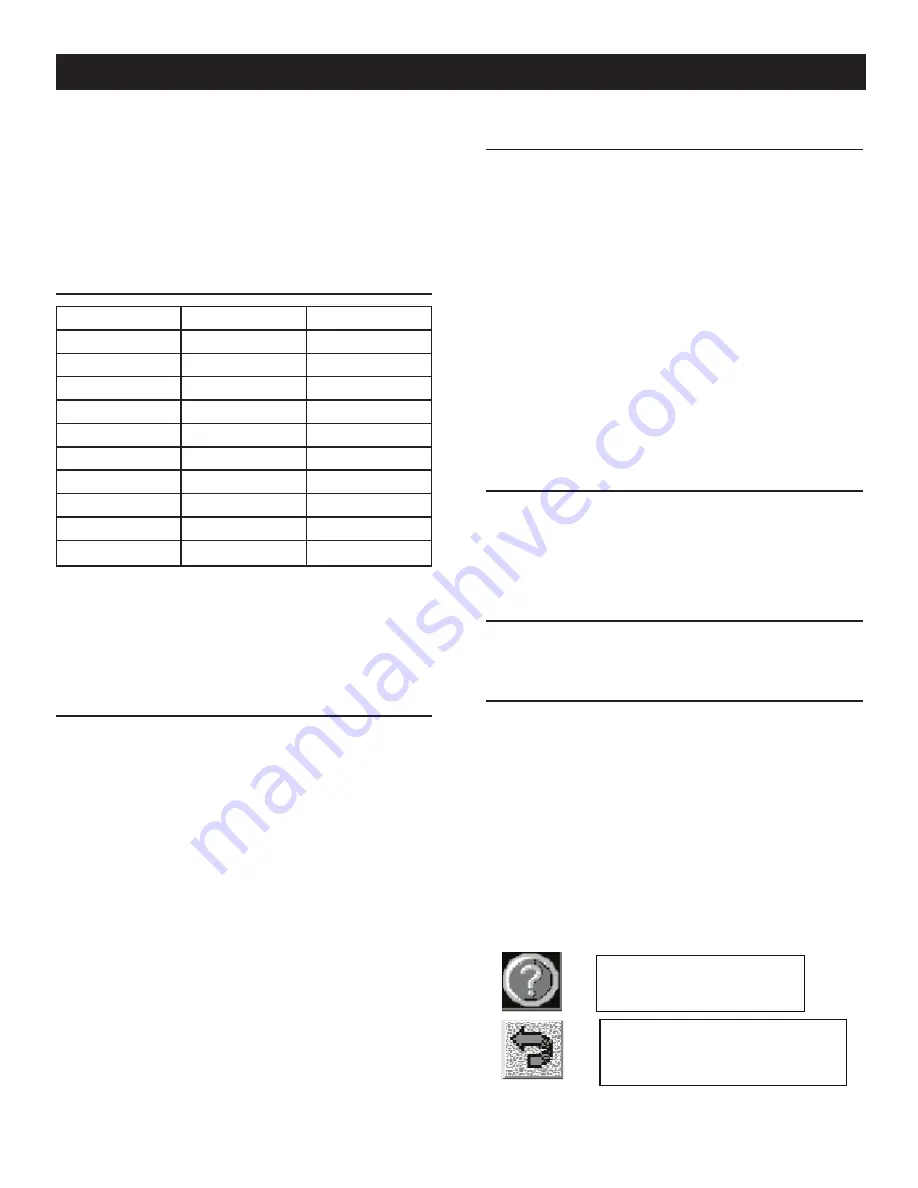
tons which allow you to either access help text for that screen 

(context sensitive help) or return to the main menu (Figures 3.23, 

3.24 and 3.25).

Figure 3.23 — Help & Return to Main

Menu Keys

RETURN TO MAIN
MENU KEY

HELP KEY

Operation

Содержание PowerManager 004975-2

Страница 1: ...MA 1 Enclosure Model 005039 1 NEMA 3R Enclosure Model 005047 1 NEMA 3R Enclosure with Heater PowerManager System Controller PM SC nOnly qualified electricians or contractors should attempt installatio...

Страница 2: ...munication Issues 9 3 10 Relay Functionality 9 3 11 Backup Modes of Operation 10 3 11 1 Introduction 10 3 11 2 Abbreviations 10 3 11 3 Documents 10 3 11 4 Standard Control System 10 3 11 5 Normal MPS...

Страница 3: ...az ard This symbol points out potential fire hazard This symbol points out potential electrical shock hazard The operator is responsible for proper and safe use of the equip ment The manufacturer stro...

Страница 4: ...Never work on the equipment when physically or mentally fatigued Inspect the generator s regularly and repair or replace all damaged or defective parts immediately Always use factory authorized parts...

Страница 5: ...to local state and national electrical and building codes Comply with regulations the Occupational Safety and Health Administration OSHA has established Also ensure that the generator s is installed...

Страница 6: ...ets with different power ratings Real time clock and calendar included user programmable to set exercisers based on date and time of day Monitoring set up of parameters and commands using New Generati...

Страница 7: ...the PC as well as Genlink this is supplied with the converter box Use the re direction software to select an unused port on your PC that will be re directed to the PC s LAN connection for example com...

Страница 8: ...ot set a leading power factor 3 1 7 SLAVE ADDRESS This is the Modbus slave ID of the generator and must correspond to the Modbus ID setting in the corresponding PM PC control panel Set all the paramet...

Страница 9: ...The base load can be programmed into the Kw setting field The power factor is fixed at 1 00 for exercise and cannot be adjusted 3 2 2 KW AND POWER FACTOR LIMITS These settings are only used to set up...

Страница 10: ...ecking any box Gen1 through 10 tells the system that the checked generator s has been intentionally taken out of service for example for maintenance The PM SC will then not expect that generator to st...

Страница 11: ...TION ISSUES Normally communication problems can be resolved with the help of either the Genlink or Touchscreen com port diagnostic displays see Figures 3 7 and 3 8 Select the diagnostic display then c...

Страница 12: ...g the generators to the bus proportion ally share load across all connected generators disconnect the generators from the Bus and shut the generators down The PM SC also accumulates data from the gene...

Страница 13: ...e for Enabling Manual Backup Operation Using GenLink connect to the PM SC Open the Configuration pull down menu and select Regulator Settings Figure 3 10 Figure 3 10 Regular Settings In the lower left...

Страница 14: ...Status After all the running generators are connected to the Bus the operator must determine what generator power is available and what the load requirements are If there is enough power available for...

Страница 15: ...procedure Go to each generator in the MPS that is in the MANUAL mode and using the generator touch screen main menu select the Diagnostics page Figure 3 17 Figure 3 17 Diagnostics Press the Cancel MA...

Страница 16: ...eration is available with PM PC and PM SC firmware version 2 2H or later Figure 3 20 The automatic backup operation consists of the normal MPS operation with the added ability of each generator PM PC...

Страница 17: ...er is available and what the maximum power needs are If there is enough power available for a given permissive to be active the PM PLS will activate the appropriate permissive signals If a generator s...

Страница 18: ...ch requests When the keyswitch is in the MAN position the PM SC will start the genera tors as though a two wire remote start had been issued This is to allow the system to be activated in the event th...

Страница 19: ...lax errors EITHER 1 Switch on the power to the unit 2 During the initialization phase a menu will appear briefly Press the CONFIG button 3 Now use the CALIBRATE button to calibrate the screen 4 Five c...

Страница 20: ...th the circuit diagram You should refer to this diagram to see that the correct input has operated Outputs from the controller are generally open collector This means that they sink current through a...

Страница 21: ...for customer use 5 User assigned 5 Free for customer use 6 User assigned 6 Free for customer use 7 Auto Led On Front Panel Led 8 User assigned 8 Free for customer use 9 Fault Led On Front Panel Led 1...

Страница 22: ...4 20ma User config channel 12 13 4 20ma User config channel 13 14 4 20ma User config channel 14 15 4 20ma User config channel 15 16 4 20ma User config channel 16 17 4 20ma User config channel 17 18 B...

Страница 23: ...E4086 in the back of this manual 1 Ensure that utility power is OFF at this point 2 Connect 18AWG or heavier double insulated wire fused at the source to terminals TB2 1 2 3 in the PM SC and run this...

Страница 24: ...tween generators should only have one end of the shield connected 7 Connect the standard telephone jack to a telephone line using an RJ 11 type cable 8 If an optional Annunciator is to be used connect...

Страница 25: ...23 Notes...

Страница 26: ...24 Notes...

Страница 27: ...25 Notes...

Страница 28: ...26 Installation Diagrams NEMA 1 Drawing No 0E7619 C...

Страница 29: ...27 NEMA 1 Drawing No 0E7619 C Installation Diagrams...

Страница 30: ...28 Installation Diagrams NEMA 3R Drawing No 0H3175 A...

Страница 31: ...29 NEMA 3R Drawing No 0H3175 A Installation Diagrams...

Страница 32: ...Parts shipment costs are reimbursed at ground shipment rates Costs related to requests for expedited shipping will be the responsibility of the customer 11 Verification of required maintenance may be...

Страница 33: ......

Страница 34: ......

Страница 35: ......

Страница 36: ......

Страница 37: ......

Страница 38: ......

Страница 39: ......

Страница 40: ......

Страница 41: ......

Страница 42: ......

Страница 43: ......

Страница 44: ......

Страница 45: ......

Страница 46: ...1 DECAL 24V SUPPLY 44 0E7438 1 DECAL POWER MANAGER SC TB6 45 062684 1 LUG SLDLSS 2 0 12 X 11 32 CU 46 067210A 1 DECAL GROUND LUG 47 091472 FT DUCT WIRING 1X1 5 6 FT 48 091472A FT COVER WIRE DUCT 1 IN...

Страница 47: ......

Страница 48: ......

Отзывы: