User Manual
Geneko GWR High Speed Router Series
13
Product Overview
Front panel
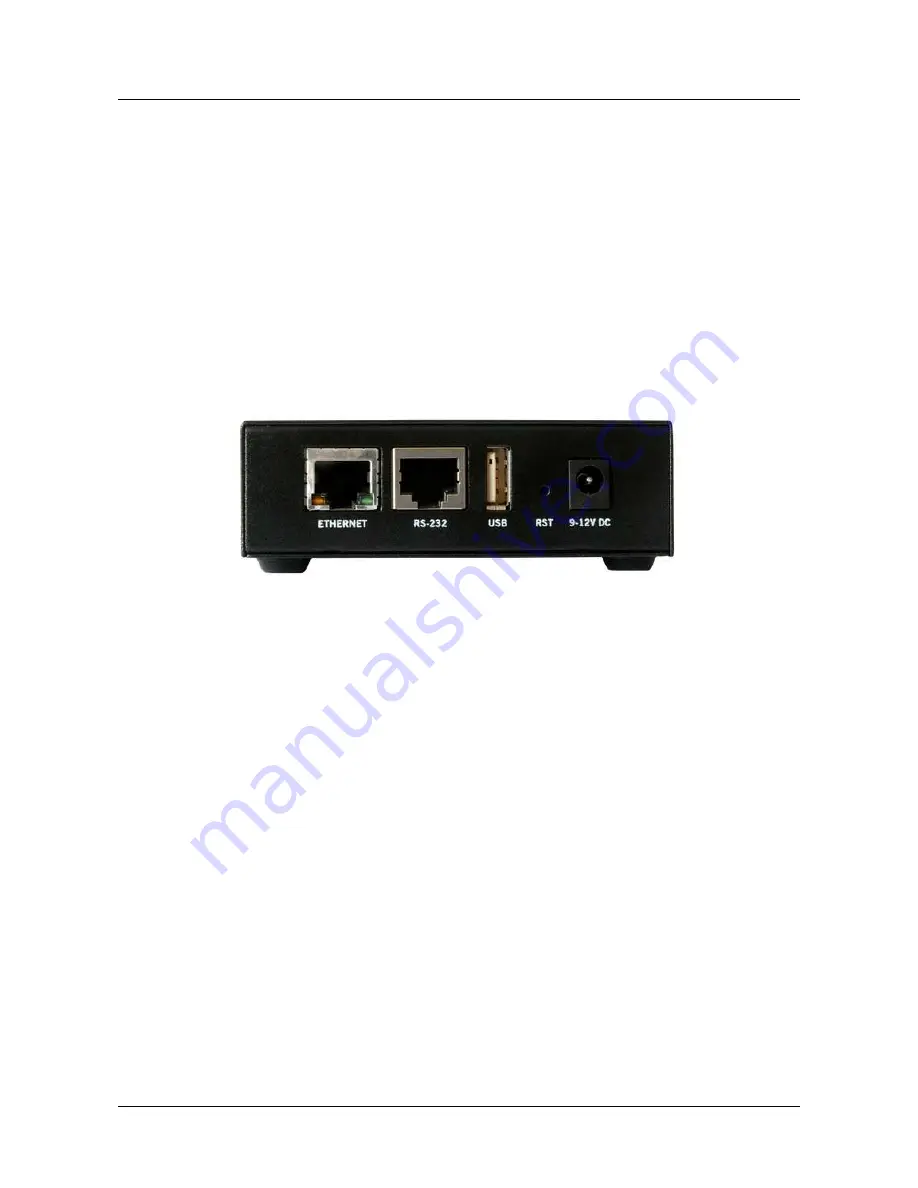
On the front panel (
Figure 2
) the following connectors are located:
•
one RJ45 connector – Ethernet port for connection into local computer network,
•
one RJ45 connector for RS232 serial communication,
•
reset button,
•
one USB connector for connection of additional device,
•
Power supply connector.
Ethernet connector LED:
•
ACT (yellow) on – Network traffic detected (off when no traffic detected),
•
Network Link (green LED) on – Ethernet activity or access point engaged.
Figure 2 – GWR-HS Router front panel
The Reset button can be used for a warm reset or a reset to factory defaults.
Warm reset:
If the GWR-HS Router is having problem connecting to the Internet, press and hold the reset
button for a second using the tip of a pen.
Reset to Factory Default:
To restore the default settings of the GWR-HS Router, hold the RESET button
pressed for a few seconds. Restoration of the default configuration will be signaled by blinks of the first and last
signal strength LED on the top panel. This will restore the factory defaults and clear all custom settings of the GWR-
HS Router. You can also reset the GWR-HS Router to factory defaults using the Maintenance > Default Settings
screen.
Back panel
On the back panel of device (
Figure 3
and
Figure 4
) the following connectors are located:
•
slot for SIM cards,
•
SMA connector for connection of the GSM/UMTS/LTE antenna.
Содержание GWR High Speed Router Series
Страница 1: ...GWR High Speed Cellular Router Series User Manual version 1 1 Date June 2014...
Страница 17: ...User Manual Geneko GWR High Speed Router Series 17 Declaration of conformity Figure 7 Declaration of conformity...
Страница 26: ...User Manual Geneko GWR High Speed Router Series 26 Figure 17 DHCP Server configuration page...
Страница 61: ...User Manual Geneko GWR High Speed Router Series 61 Figure 38 Modbus gateway configuration page...


